4. Sensors Architecture: Top-carrier Robot
4.1. Introduction
Sensors Architecture Description
The sensor architecture adopts a modular approach to accommodate diverse use cases. In this configuration designed for flat-bed (top-carrier) AMR/AGVs, all stereo cameras support robust perception, while mono cameras facilitate teleoperation and sensor-to-sensor calibration.
This architecture comprises of four stereo and four mono cameras.
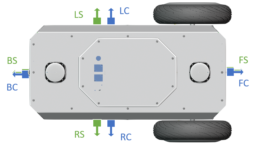
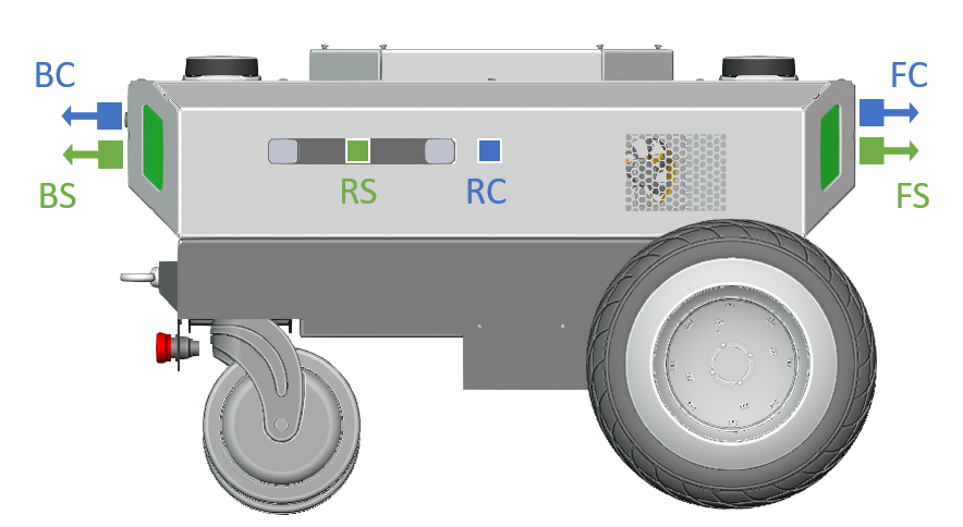
Acronym |
Camera Designation |
|---|---|
FS |
Front stereo |
BS |
Back stereo |
RS |
Right stereo |
LS |
Left stereo |
FC |
Front camera |
BC |
Back camera |
RC |
Right camera |
LC |
Left camera |
4.2. Stereo-vision Cameras Coverage Requirements
4.2.1. Surround Coverage Requirements
Req ID: |
Ground Visibility |
27461095 |
Stereo camera(s) arrangement shall be able to see the ground plane from a distance of < 1m from the foremost and the back-most AMR surfaces across the AMR width. Stereo camera(s) arrangement shall be able to see the ground plane from a distance of < 1m from the leftmost and the rightmost AMR surfaces across the AMR length. 
|
Req ID: |
Combined HFOV |
27461115 |
Stereo camera(s) arrangement shall provide 360 degrees coverage around the AMR. 
|
4.2.2. Mounting Requirements
Req ID: |
Pitch Range |
27461119 |
Any stereo camera pitch angle shall be between -10 and 5 degrees. |
Req ID: |
Z-range |
27461136 |
Any stereo camera Z vertex shall be < 0.5m height. |
4.3. Mono Cameras Coverage Requirements
4.3.1. Surround Coverage Requirements
Req ID: |
Ground Visibility |
27461145 |
Camera(s) arrangement shall be able to see the ground plane from a distance if < 0.2m from the foremost and the back-most AMR surfaces across the AMR width. Camera(s) arrangement shall be able to see the ground plane from a distance < 0.2m from the leftmost and the rightmost AMR surfaces across the AMR length. 
|
Req ID: |
Combined HFOV |
27461155 |
Camera(s) arrangement shall provide 360 degrees coverage around the AMR. 
|
4.3.2. Mounting Requirements
Req ID: |
Pitch Range |
27461163 |
Any camera pitch angle shall be between -10 and 5 degrees. |
Req ID: |
Z-range |
27461167 |
Any camera Z vertex shall be < 0.5m in height. |
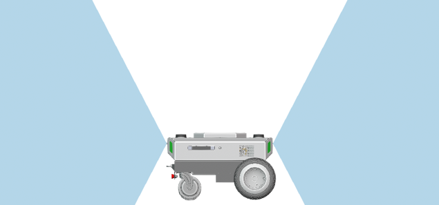
Sensors Mounting Example
Below is an implementation example for the camera belt.
The stereo cameras’ coverage is depicted in the images below:
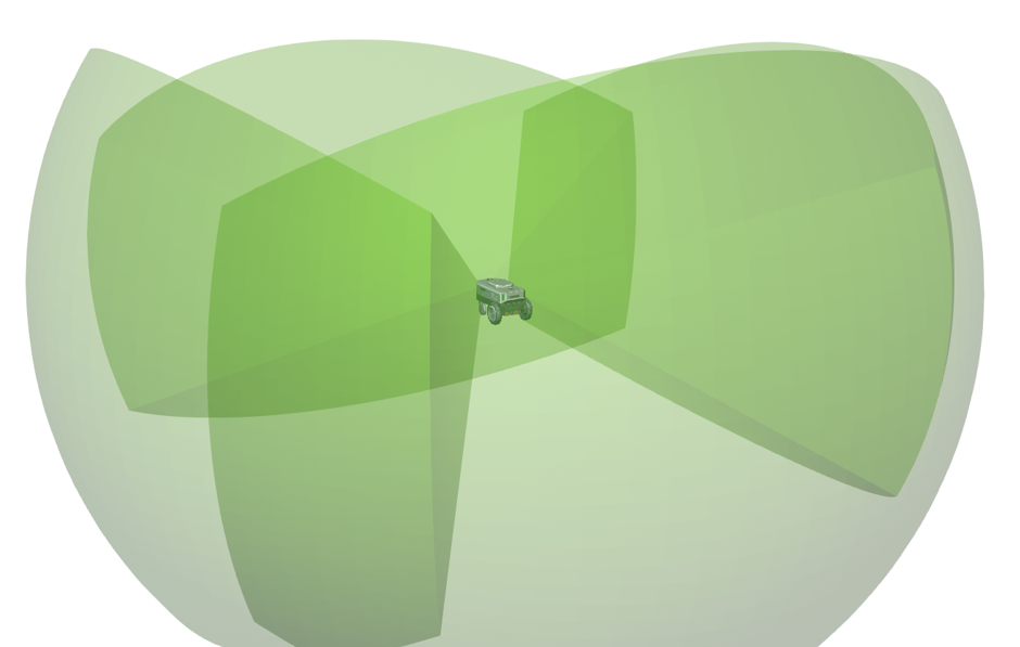
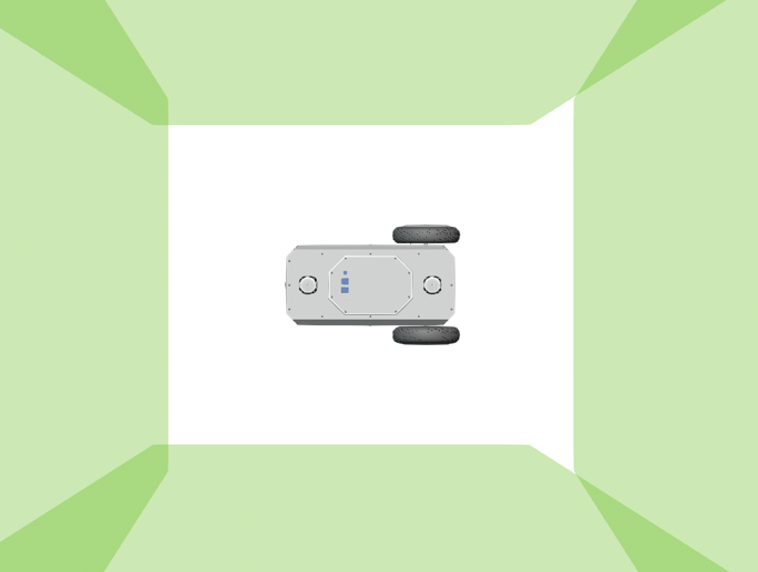

The sensors mounting locations and angles are summarized in the following table:
X [m] |
Y [m] |
Z [m] |
Pitch [deg] |
Yaw [deg] |
Roll [deg] |
|
FS |
-0.017 |
0.075 |
0.344 |
0 |
0 |
0 |
BS |
-0.681 |
-0.075 |
0.344 |
0 |
180 |
0 |
RS |
-0.398 |
-0.15 |
0.344 |
0 |
-90 |
0 |
LS |
-0.548 |
0.15 |
0.344 |
0 |
90 |
0 |
Note
Hawk vertex, aligned with the left lens center, was chosen for representation of Hawk locations. Please refer to Hawk datasheet for more information.
The mono cameras’ coverage is depicted in the images below:
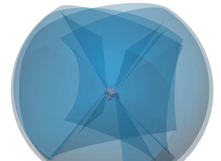
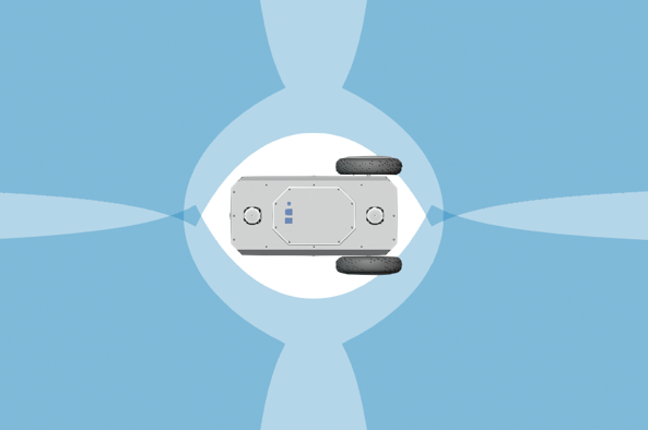
The sensors mounting locations and angles are summarized in the following table:
X [m] |
Y [m] |
Z [m] |
Pitch [deg] |
Yaw [deg] |
Roll [deg] |
|
FC |
-0.01 |
0 |
0.374 |
0 |
0 |
0 |
BC |
-0.688 |
0 |
0.374 |
0 |
180 |
0 |
RC |
-0.349 |
-0.157 |
0.344 |
0 |
-90 |
0 |
LC |
-0.349 |
0.157 |
0.344 |
0 |
90 |
0 |
Note
Owl vertex was chosen for representation of Owl locations. Please refer to Owl datasheet for more information.
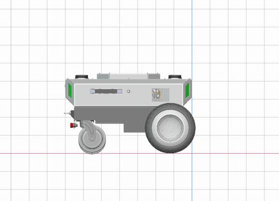
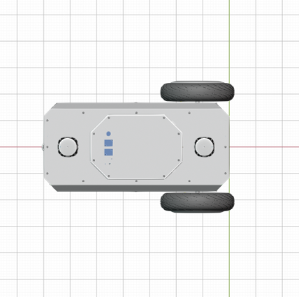
For reference, the AMR used in this example is shown on a 10cm x 10cm grid: