Validating Isaac ROS Visual SLAM on a Robot#
Overview#
This document outlines a procedure that can be used to validate the successful installation and configuration of Isaac ROS Visual SLAM on real hardware.
Prerequisites#
[ ] NVIDIA Jetson
[ ] Standalone computer with ROS data visualization tool (RViz, Foxglove, etc.)
[ ] Compatible stereo camera
[ ] Enough space to navigate (~40m loop)
[ ] Tape measure
Prepare Physical Environment#
Examine the designated testing area and identify a single, non-intersecting loop whose path length is approximately 40 meters. This is the path along which the camera is moved and tracked using Isaac ROS Visual SLAM.
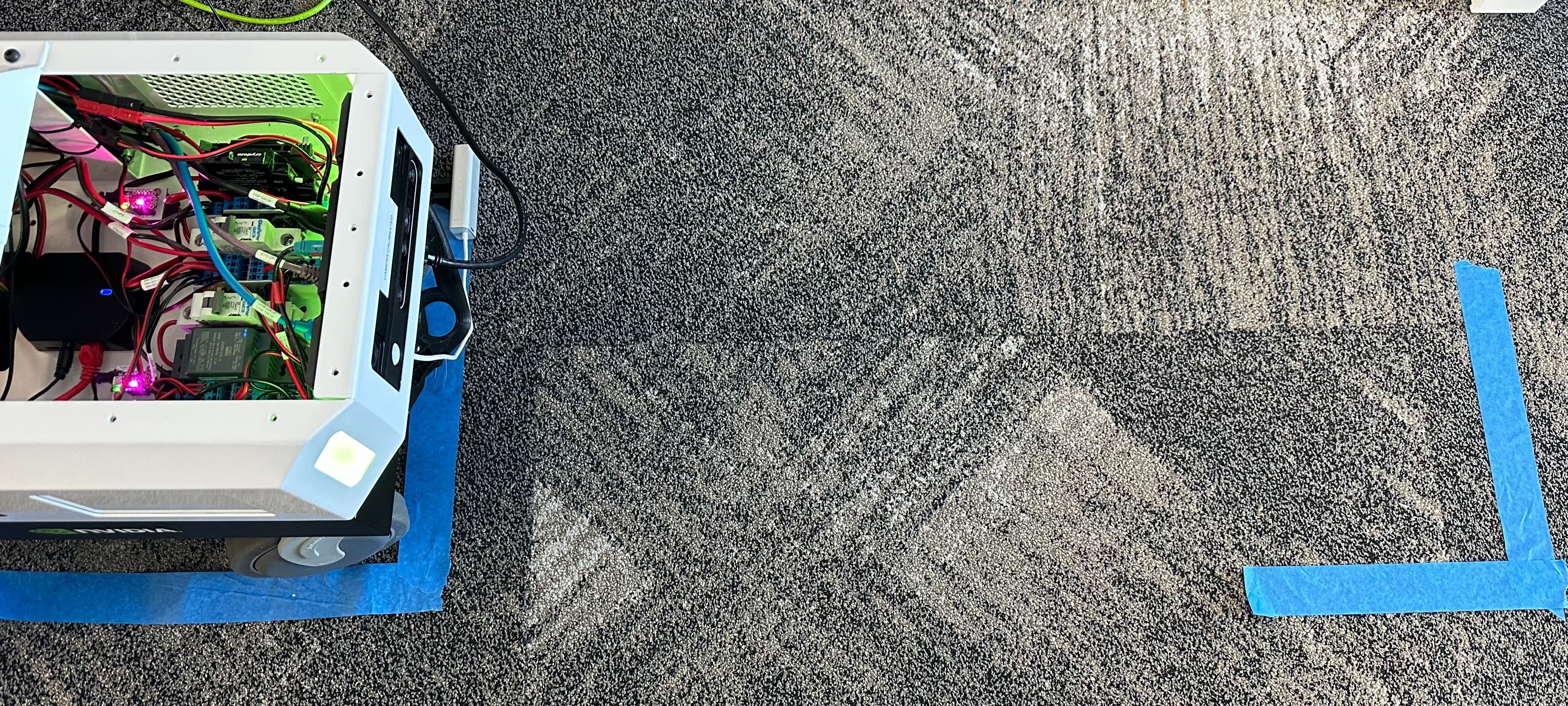
Define a starting pose along the identified loop. Label this pose with masking tape or a different marker.
One possible approach is to mark an L-shape on the floor, aligning the camera’s position and orientation to the corner of the shape.
Using a measuring tool, measure out a secondary pose along the loop that is exactly 1 meter along the forward axis from the starting pose. Label this pose in the same manner.
Download and Configure Packages#
On each of the Jetson and standalone computers, set up your development environment by following the dev setup instructions.
Note
${ISAAC_ROS_WS}is defined to point to/ssd/workspaces/isaac_ros-dev/or~/workspaces/isaac_ros-dev/.Set up your stereo camera and connect it to the Jetson:
For RealSense cameras, complete the RealSense setup tutorial.
On both devices, clone this repository under
${ISAAC_ROS_WS}/src.cd ${ISAAC_ROS_WS}/src
git clone -b release-4.5 https://github.com/NVIDIA-ISAAC-ROS/isaac_ros_visual_slam.git isaac_ros_visual_slam
Build ROS Workspace#
On the Jetson, activate the Isaac ROS environment in a new terminal:
isaac-ros activateInside the container, install this package’s dependencies.
sudo apt-get update
sudo apt-get install -y ros-jazzy-isaac-ros-visual-slam
Select and Start ROS Visualization Tool#
Ensure that the standalone computer and Jetson device are on the same network.
On the standalone computer, start RViz from the provided configuration file:
Start the Isaac ROS environment for RViz on the standalone computer:
isaac-ros activate(Optional) Configure the
ROS_DOMAIN_IDenvironment variable on both devices to eliminate any cross-talk from other ROS nodes on the same network.In each terminal on each device:
export ROS_DOMAIN_ID=5 # Any number between 1-101; use the same number for each terminal
Note
This environment variable must be set in each terminal, on both the Jetson and the standalone computer.
Install RViz:
sudo apt-get install -y ros-jazzy-rviz2
source /opt/ros/jazzy/setup.bash
From this terminal, run RViz2 to display the output:
rviz2 -d $(ros2 pkg prefix isaac_ros_visual_slam --share)/rviz/default.cfg.rviz
On the standalone computer, start logging the estimated transform:
Attach another terminal to the running container for
tf2_echo:isaac-ros activateFrom this terminal, run
tf2_echoto display the transform between the/mapframe and the appropriate base frame (e.g.,/camera_linkfor RealSense):ros2 run tf2_ros tf2_echo map base
Run Isaac ROS Visual SLAM and Monitor Results#
Visual Odometry Test#
The purpose of this test is to validate that the system is able to provide accurate measurements of the robot’s local motion.
Initialize the camera at the marked starting pose.
On the Jetson, run the Isaac ROS Visual SLAM launch file for your camera type:
RealSense:
ros2 launch isaac_ros_visual_slam isaac_ros_visual_slam_realsense.launch.py
The
/map,/odom, and camera frames must all be initialized to the starting pose.Carefully move the camera straight forward to the marked secondary pose.
On the standalone computer and within the
tf2_echoterminal, note the latest transform reported between/mapand the appropriate camera frame.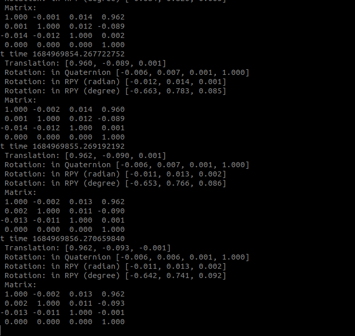
Validate orientation:
Validate that the orientation error between the measured rotation unit quaternion and the expected rotation unit quaternion (
[0 0 0 1]) is less than 15 degrees. This error can be calculated using the process explained here:\[q_{measured} = w_m + x_m i + y_m j + z_m k\]\[q_{expected} = w_e + x_e i + y_e j + z_e k\]\[2 \arccos(w_m w_e + x_m x_e + y_m y_e + z_m z_e) \leq 15 \degree\]Validate translation:
Verify that the magnitude of the measured translation is within 5 centimeters of the expected translation (1 meter):
\[0.95 \text{m} \leq \|t_{measured}\| \leq 1.05 \text{m}\]
If all real-world measurements correspond to the reported estimates within the expected tolerance, the Visual Odometry test is a success.
Loop Closure Test#
The purpose of this test is to validate that the system is able to appropriately realign the estimated pose path to previously-seen features.
Initialize the camera at the marked starting pose.
On the Jetson, run the Isaac ROS Visual SLAM launch file for your camera type:
RealSense:
ros2 launch isaac_ros_visual_slam isaac_ros_visual_slam_realsense.launch.py
Validate that the
/map,/odom, and camera frames are all initialized to the starting pose.Carefully move the camera along the predetermined 40m path.
Note
To maximize the accuracy of this test, ensure that dynamic obstacles are removed from the robot’s field of view. If a nontrivial dynamic obstacle is introduced while the robot is performing the loop, you must restart this test.
As the camera nears the completion of its first lap, move the camera in a small circle with the radius of ~0.5m around the origin of the starting pose. This step helps ensure that the previously-seen visual features are recognized and matched.
Place the camera at rest, taking care to precisely align it with the floor marker indicating the starting pose.
On the standalone computer and within the RViz window, ensure that a nontrivial number of visual features now appear red. Additionally, ensure that the camera frame appears nearly coincident with the
/mapframe.Note
It is acceptable for the
/odomframe to jump around significantly with respect to the/mapframe. For the purposes of this test, only the transform between the/mapand camera frames is relevant. For additional information about the design intent behind these frames, see REP-0105.On the standalone computer and within the
tf2_echoterminal, note the latest transform reported between/mapand the appropriate camera frame.Validate orientation:
Validate that the orientation error between the measured rotation unit quaternion and the expected rotation unit quaternion (
[0 0 0 1], because the path is a closed loop) is less than 15 degrees. This error can be calculated using the process explained here:\[q_{measured} = w_m + x_m i + y_m j + z_m k\]\[q_{expected} = w_e + x_e i + y_e j + z_e k\]\[2 \arccos (w_m w_e + x_m x_e + y_m y_e + z_m z_e) \leq 15 \degree\]Validate translation:
Validate that the magnitude of the measured translation is within 2 meters (5% of the 40m path length) of the expected translation (0 meters, because the path is a closed loop):
\[0 \text{m} \leq \|t_{measured}\| \leq 2 \text{m}\]
If all real-world measurements correspond to the reported estimates within the expected tolerance, the Loop Closure test is a success.
Next Steps#
Troubleshooting#
If any step of the tests did not succeed, then there might be a configuration error with your system. Follow these troubleshooting suggestions.
If the prepared troubleshooting steps are unable to resolve the test failure, contact your NVIDIA support representative and file an issue report with all relevant details.
Integrating Isaac ROS Visual SLAM#
While the Isaac ROS Visual SLAM node exposes a multitude of
interfaces,
the core way to consume the node’s output is through the reported
transform between the /map and base frame.
Based on your robot’s precise specifications, you can set up a static
transform publisher or URDF-based publisher that connects the camera
frame to a relevant planning frame on the robot (typically named
/base_link). Then, your navigation stack can use the transform
between /base_link and /map to plan movements within the local
space.
Consider further augmenting your robot’s navigation stack with other Isaac ROS packages, such as Isaac ROS Nvblox for 3D reconstruction.