Tutorial for Gear Assembly with Contact Rich Insertion Policy and cuMotion#
Warning
This tutorial uses an experimental RL model that may or may not perform as expected.
Overview#
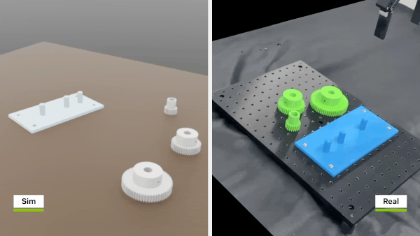
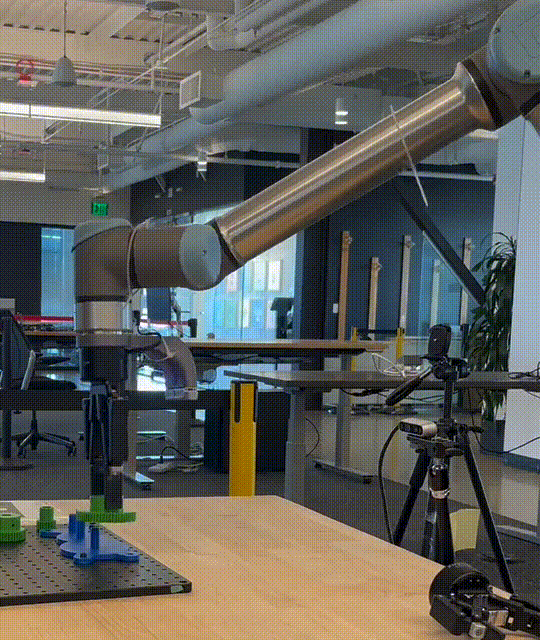
This tutorial walks through the process of inserting gears into a peg stand through a contact rich motion policy using the following packages. This tutorial focuses on deploying a pre-trained policy using Isaac ROS. A separate tutorial covering how to train such a policy in Isaac Lab will be available soon.
Isaac ROS Segment Anything or Isaac ROS Segment Anything 2 for image segmentation
Isaac ROS FoundationPose for object 3D pose estimation
Isaac ROS Nvblox for 3D scene reconstruction
Isaac ROS cuMotion for motion planning with obstacle avoidance
Isaac ROS Object Attachment for estimating the object collision spheres
Isaac ROS UR DNN Policy for inserting the gear into the peg stand.
This tutorial assumes the following:
A Universal Robots manipulator (UR10e) and a Robotiq two-finger gripper (2F-140 or 2F-85). PolyScope >=5.23 is required for the
isaac_manipulator_ur_dnn_policypackage. This is available for download on UR’s website. Instructions on how to update PolyScope can be found here.A RealSense camera. We have tested with all the cameras supported by Isaac ROS (
D455andD435).D415is not supported by Isaac ROS currently.In this tutorial, we use gear objects and
pretrainedpolicies for both gripper with the UR10e robot. These objects are installed using the isaac manipulator asset bringup package. It is part of theisaac_manipulator_ur_dnn_policyquickstart.tar.gzpackage.Tabletop scene is static when the object is being picked and placed.
Tabletop scene is static when the object detection and pose estimation are being performed.
3D print the assets for gear assembly, these assets can be found here.
This tutorial uses the following action servers:
Object detection server: For detecting objects in the scene.
Segmentation server: For generating a segmentation mask of the selected object in the scene.
Pose estimation server: For estimating the pose of the object in the scene.
Object info server: For wrapping the object detection and pose estimation servers. This provides a common interface for getting the object information like the object pose or 2D bounding box.
Pick and place action server: For triggering pick and place pipeline.
Planner server: For planning with cuMotion.
Object attachment server: For object attachment and detachment during planning.
Gripper server: For controlling the gripper via ROS 2 actions.
Gear assembly server: For triggering gear assembly pipeline.
Insertion server: For inserting the gear into the peg stand. This will internally call the inference code to execute the policy.
Prerequisites#
Follow the setup instructions in Setup Hardware and Software for Real Robot.
3D print the assets for gear assembly, these assets can be found here.
Successfully validated the calibration of your UR robot by running the calibration validation test mentioned at the end of the calibration documentation.
Successfully performed the gear insertion mentioned in the Single Gear Insertion Policy tutorial tutorial.
Tutorial Walkthrough#
When the pipeline is triggered using the action call mentioned below, the following things happen:
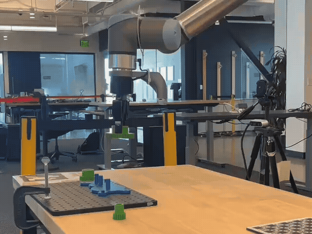
The user is prompted to click on the peg stand to estimate the pose of the peg stand.
The user is prompted to click on the gear to insert.
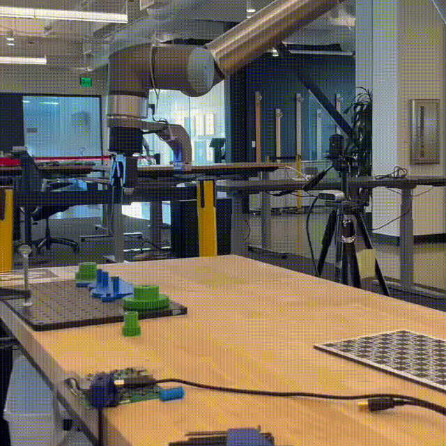
The gear is inserted into the peg stand.
The user is prompted to do the same for the remaining gears.
In the background, the following happens:
Using state of the art perception models, the pose of the different gears and peg stand is segmented (using Segment Anything or Segment Anything 2) and the output mask generated along with the depth and image is sent to FoundationPose to estimate their 3D pose. The depth backend is also similarly flexible and the user can choose between the depth offered by the
Realsensecamera, or depth produced byESSorFOUNDATION_STEREOnetworks.The robot then does a pick and place motion and places the gripper above the peg stand of the 3 gears in sequence, and inserts them into the peg stand using a neural skill policy.
The entire workflow is orchestrated by the gear assembly server.
It uses the pick and place pipeline with bells and whistles (object attachment, collision avoidance, etc.) before inserting the gears into the peg stand.
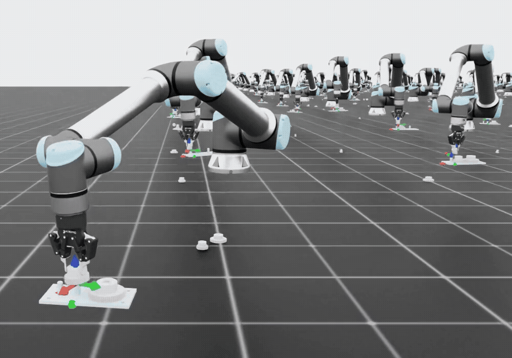
The insertion policy is a RNN based policy that receives joint states, velocities as input at 30 Hz and outputs joint space target actions that are also fed into a custom controller at 30 Hz. It is trained on top of Isaac Sim and Isaac Lab using a Reinforcement Learning algorithm.
We also develop a custom controller for the UR robot that can be used for impedance controller that results in executing safe motions on the robot. It is an impedance based controller similar to the Franka robot. It runs at 500 Hz.
One can find more details about the technique used for peg insertion in this blog post.
FAQs#
Why do we need contact rich insertion policies ?
Contact rich insertion policies are necessary because they allow the robot to adapt to the environment during execution. This is important because the environment is constantly changing during execution and the robot needs to be able to adapt to these changes.
Why was Reinforcement Learning used to train the policy ?
Reinforcement Learning was used to train the policy because it allows the robot to learn from experience and discover novel strategies that are hard to program in the software. This is important since we have noticed calibration errors, depth estimation errors can lead to a pose estimation for the goal to be off by about 10 mm, which can lead to failure of hard coded policies. We observe that RL policies are resilient to these failure cases.
What is the benefit of using Reinforcement Learning over classical impedance control ?
RL policies rely on low level controllers, such as impedance control, to execute the policy actions. Hence, we are using impedance control for the gear policy execution. The key advantage of
RLis that it can automatically discover effective strategies for accomplishing a task, rather than relying on manually programmed heuristics. This makesRLa more generalizable and adaptive approach, capable of learning behaviors for different setups, contact conditions, or part variations, something that classical impedance control alone cannot easily achieve without redefining heuristics/tuning.
Can this technique only used for gear assembly ?
No, this technique can be used for any tasks that require contact rich insertion and can be simulated.
Can this technique be used for other robots ?
Yes, this technique can be used for other robots. However, the user will need to train their own policy with their custom robot and scene.
Is the training procedure available ?
Not currently, but the training procedure will be open sourced in Isaac Lab soon. This tutorial focuses on deploying a pre-trained policy using Isaac ROS. A separate tutorial covering how to train such a policy in Isaac Lab will be available soon.
What was the main learning from this sim2real transfer that can be applied to other tasks ?
The main learning are to quantify errors (in calibration, pose estimation, depth estimation, robot controller steady state errors) and make sure that the same is true or close to true in the simulation used for training the policy. We share our tests that the user can look at and read more about in the Isaac for Manipulation Testing Guide and calibration section.
Tutorial#
Gear Assembly Specific Configuration Parameters#
Refer to the Create Manipulator Configuration File section for information on what parameters to tune for gear assembly.
The parameters of importance are:
gear_assembly_model_path: Path to the gear assembly modelgear_assembly_model_file_name: Name of the gear assembly model file model_gripper_85.pt or model_gripper_140.pt. Please refer to theisaac_manipulator_ur_dnn_policyquickstart.tar.gzpackage for the model and gear asset files.gripper_type: Type of the gripper robotiq_2f_85 or robotiq_2f_140.setup: Setup of the robot, the setup will reference the camera calibration and sensor information.moveit_collision_objects_scene_file: Path to the MoveIt collision objects scene file.cumotion_urdf_file_path: Path to the cuMotion URDF file.cumotion_xrdf_file_path: Path to the cuMotion XRDF file.gear_assembly_enable_recording: Enable recording of the gear assembly ROS bag.add_ability_to_toggle_inference: Enable the ability to toggle inference.grasps_file_path: Path to the grasps file path, theisaac_manipulator_robot_description/configfolder has grasp files for the large gear for the robotiq_2f_140 and robotiq_2f_85 grippers.end_effector_mesh_resource_uri: Path to the end effector mesh resourceuri. It is specific to each gripper.srdf_path: Path to the SRDF file. This is specific to each gripper.gear_assembly_ros_bag_folder_path: Path to the gear assembly ROS bag folder.gear_assembly_enable_recording: Enable recording of the gear assembly ROS bag.depth_type: Type of the depth estimation.REALSENSE,ESS_FULL,FOUNDATION_STEREOare the various options offered.enable_dnn_depth_in_realsense: Enable DNN depth in RealSense. If this is set totrue, thenESS_FULLandFOUNDATION_STEREOcan be used. Otherwise, defaultREALSENSEdepth is used.gear_assembly_model_frequency: Frequency of the gear assembly model in Hz. Note that we train our policies at 30Hzand deploy them at 30Hzas well.gear_assembly_offset_for_place_pose: Offset for the place pose in meters. Note that we use a value of0.34for therobotiq_2f_140gripper and0.32for therobotiq_2f_85gripper.enable_nvblox: EnableNvBloxfor 3D scene reconstruction and dynamic collision avoidance. Note that we do not enable this by default to keep system load low, but the user can experiment with it if they would like.ur_calibration_file_path: Path to the UR calibration file. Please refer to this documentation.
Examples of configuration files for the two grippers are provided in the
isaac_manipulator_bringuppackage.
Gear Assembly Specific On Robot Tests#
Since gear assembly is a complex workflow that needs to have strict tolerances for pose estimation and camera calibration, we have a separate test suite for gear assembly. Users can run the following command to run the gear assembly specific tests:
Run the calibration validation test mentioned at the end of the calibration documentation.
After running the tests please validate that your camera does not have more than 1 cm error (more information is provided in the tests).
Run this test to verify pose estimation and depth estimation accuracy.
export ENABLE_MANIPULATOR_TESTING=manual_on_robot
launch_test $(ros2 pkg prefix --share isaac_manipulator_bringup)/test/test_pose_estimation_error_test.py
Note
This test will make the robot go to a pose that is on top of the peg stand. Then the user can visually estimate what the pose error is of the wrist_3_link w.r.t to the peg stand shaft of the large gear.
Warning
If this test does not lead to the robot being on top of the peg stand with less than 1 cm error, then there is a problem with the pose estimation or the camera calibration. The gear insertion is unlikely to work in this case. We train the policy with up to 1 cm of noise in the pose estimation.
Run the pose estimation repeatability tests to validate that the pose estimation is repeatable.
export ENABLE_MANIPULATOR_TESTING=manual_on_robot
bash ${ISAAC_ROS_WS}/src/isaac_manipulator/isaac_manipulator_bringup/test/compare_pose_estimation_results.sh
Note
This test will perform 10 pose estimations requests with different depth backends and then perform repeatability analysis. This will ensure that the pose estimation does not have issues with flips or flickering.
Run the gear insertion tests in isolation before running the entire gear assembly workflow. This test is referenced in this documentation.
After you have validated that all these tests are passing, you can run the entire gear assembly workflow.
Please calibrate the robot using the instructions in this documentation.
After calibrating, please edit the calibration file path in the manipulator configuration file to the path to the calibration file for your robot. The parameter to edit is
ur_calibration_file_path.
Note
If you are using the robotiq_2f_140 gripper, please make this change in the $ISAAC_ROS_WS/isaac_ros_assets/isaac_manipulator_ur_dnn_policy/params/env.yaml file.
action_scale_joint_space:
- 0.0325
- 0.0325
- 0.0325
- 0.0325
- 0.0325
- 0.0325
The default value is 0.025 which works well with the robotiq_2f_85 gripper but the default value for the robotiq_2f_140 gripper needs to be 0.0325 to overcome the higher static friction (striction) and slight changes in the training process. This is a hyper parameter that will be removed in future releases as we add policy updates in upcoming releases.
Run Launch Files and Deploy to Robot#
We recommend setting a ROS_DOMAIN_ID via export ROS_DOMAIN_ID=<ID_NUMBER> for every
new terminal where you run ROS commands, to avoid interference
with other computers in the same network (ROS Guide).
We recommend using Cyclone DDS for this tutorial when trying on real robot for better performance.
To enable Cyclone DDS, run the following command in each terminal (once) before running any other command.
export RMW_IMPLEMENTATION=rmw_cyclonedds_cpp
On the UR teach pendant, ensure that the robot’s remote program is loaded and that the robot is paused or stopped for safety purposes. Also make sure that the Robotiq gripper is set to “User” in the Tool I/O settings. This allows the software to control the gripper.
Open a new terminal and activate the Isaac ROS environment:
isaac-ros activateUpdate the configuration file for Isaac for Manipulation to use the gear assembly workflow.
Change the
workflow_typetoGEAR_ASSEMBLYin the manipulator configuration file.Launch the example:
ros2 launch isaac_manipulator_bringup workflows.launch.py \
   manipulator_workflow_config:=$(ros2 pkg prefix --share isaac_manipulator_bringup)/params/ur10e_robotiq_2f_140_gear_assembly.yaml
The
manipulator_workflow_configparameter points to the manipulator configuration file. Please refer to Create Manipulator Configuration File section. Also refer to the documentation in the above section on what parameters to change for this workflow.Open another terminal and activate the Isaac ROS environment:
isaac-ros activateWait for the terminal log to show
cuMotion is ready for planning queries!On the UR teach pendant, press play to enable the robot.
Trigger the gear assembly workflow:
ros2 action send_goal /gear_assembly isaac_manipulator_interfaces/action/GearAssembly {}
First make the
rqt_image_viewtopic the same as the one mentioned manipulator configuration file. (/input_points_debug) and the camera topic needs to be/camera_1/color/image_raw.Note
The
rqt_image_viewtopic is the topic that is used to visualize the image. If the camera topic is not available, then the user can click the refresh button to refresh theGUI.Then when prompted in the test, click on the gear base (the stand on which the gears will be inserted)
Then, after user clicks on the peg stand, the workflow will estimate the 3D pose of the peg stand.
Once done, the test will prompt the user to click on the largest gear to begin the pick and insert progress.
Click on the large gear in
rqt_image_view.Once clicked, the robot should pick the gear up and bring it on top of the peg stand.
The log from the gear assembly orchestrator will prompt that the user should click on the next gear to insert.
After insertion has completed, the policy should prompt the user to click on the next gear to insert. (click the small gear)
Follow the same process as above and insert the small gear.
The test will prompt the user to click on the next gear to insert. (click the medium gear)
Follow the same process as above and insert the medium gear.
The test should end after insertion the medium gear.
Why does the robot fail to insert the gear ?#
This is a loaded question but it can be decomposed to one of the following issues.
Calibration Errors
The pose that is being sent to the insertion policy might have calibration errors of more than 1 cm. We train our policies to be robust to 1 cm error in pose estimation but larger errors are unlikely to work. One can verify how bad the calibration error is by running the calibration validation test mentioned at the end of the calibration documentation.
As we show in the documentation, the error shown is around 1 cm at the worst case scenario.
Pose Estimation Errors and Pose Estimation Repeatability, Controller Steady State Errors
The pose estimation is a function of the calibration, the depth estimation and the segmentation mask quality.
To perform an integration test, and move to the robot on top of the pose you would like to insert to, please run a test that will do the pose estimation then use cuMotion to move the robot on top of that pose with some z offset.
To run the test, that will do the pose estimation and then use cuMotion to move the robot on top of that pose with some z offset, please run the following command:
export ENABLE_MANIPULATOR_TESTING=manual_on_robot
launch_test $(ros2 pkg prefix --share isaac_manipulator_bringup)/test/test_pose_estimation_error_test.py
This will run a test that will do the pose estimation and then use cuMotion to move the robot on top of that pose with some z offset.
Note
The user is expected to click on top of the peg stand in the rqt_image_view topic, for the segmentation mask to be generated and the pose estimation to be performed.
Warning
If the robot has an error of greater than 1.5 cm, then there is a problem with the calibration error
or the depth quality of the camera. Please experiment with ESS and FOUNDATION_STEREO instead of stock Realsense depth.
You can easily change the depth quality by changing the test configuration file that is used to run the test.
As shown in above sections, you can also run the pose estimation repeatability tests to validate that the pose estimation is repeatable.
This test will also test the controller steady state error as a result of using cuMotion and then the controller to execute the trajectory. We do not have an isolated tests to verify the steady state error of the impedance controller but have verified it to be sub cm and sub degree in accuracy.
Please note that controller steady state error can definitely be a huge cause of failure for gear insertion and it is recommended to calibration your UR robot before running any tests and filling up the calibration_file_path parameter in the manipulator configuration file.
Out of distribution start state of the robot before gear insertion
The policy for insertion is trained with only a specific number of Inverse Kinematics (IK) starting solutions. This means that for an UR robot which is a 6 DOF robot and has 8 unique IK solutions for any given pose- it is likely that the user can start the insertion from an out of distribution position.
Given below is the home position we use before running the insertion test detailed in the this section.
Joint Position: Base: 150.93 | Shoulder: -50.19 | Elbow: 88.87 | Wrist 1: -131.34 | Wrist 2: -89.41 | Wrist 3: -116.80
Here is a picture of the same home pose stored in the control box of the robot.
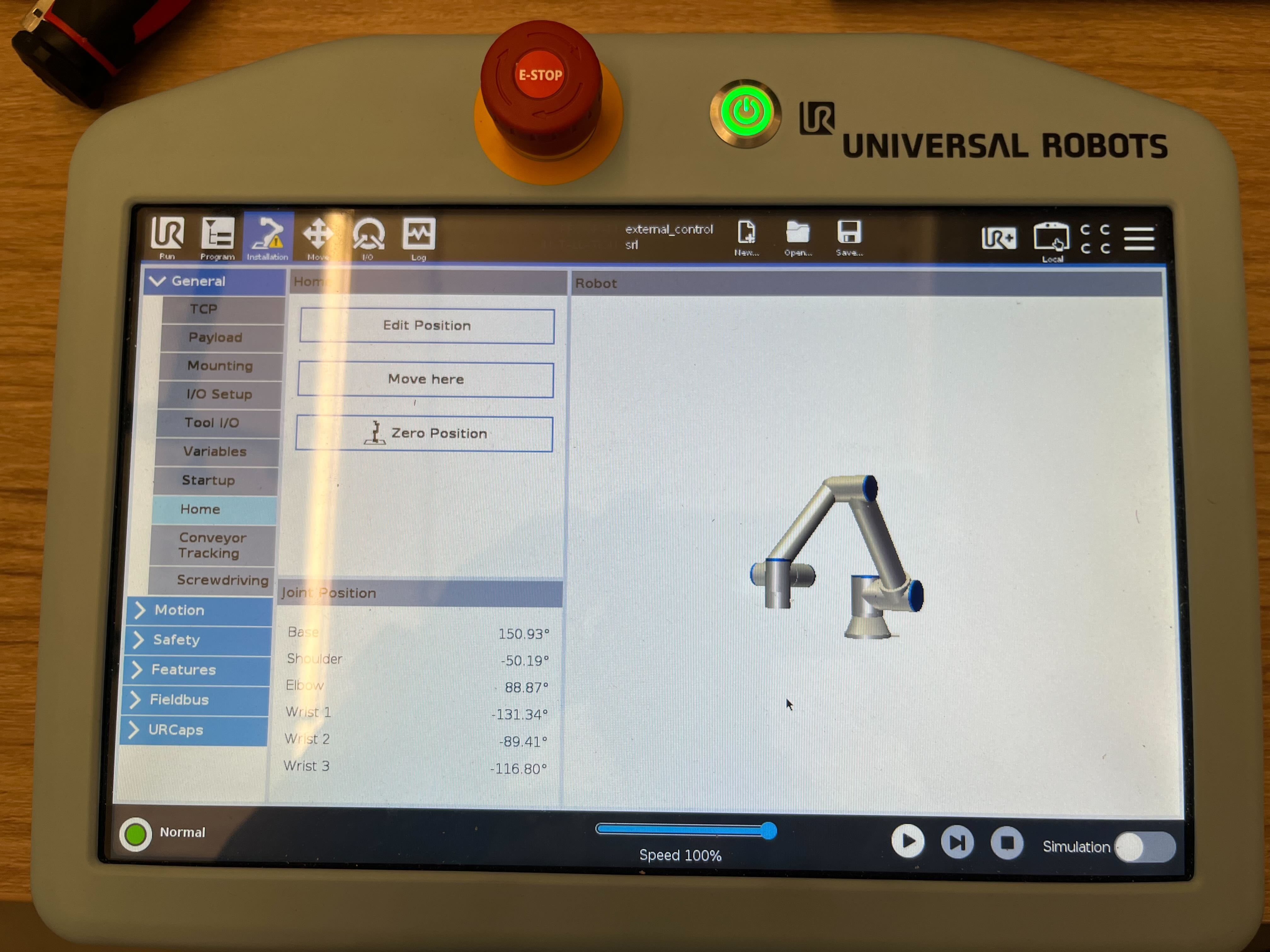
We make sure that the robot is not in an OOD start state by using the joint state planner inside of cuMotion that constrains the trajectory generated to end at a place close to the home pose.
That is the reason why we set the parameter gear_assembly_use_joint_state_planner to true in the manipulator configuration file.
The other thing to make sure is that the pose we are sending to the insertion policy is also in distribution. We make sure of this by having a check at the policy level where before any inference, we check if the pose in in distribution. If you see a log message like the one shown below, then the pose is not in distribution and the gear insertion is unlikely to work.
[WARNING] [observation_encoder_node]: target position out of distribution
Note
The other thing to be aware of when running the policy for the 140 gripper is that the policy is trained with the wrist_3_link angle being between -10 degrees and -50 degrees.
If the angle is positive and out of the range the performance and success rates will be much worse.
In the future, we will train the policy over a much wider distribution of joint angles and make it more robust to these changes.
We ask the user to manually change the angle to be inside this range during this workflow presently.
Static friction of the robot is too high that the policy is not able to overcome.
This stems from the root cause that the friction behavior in the simulation is not similar to the real robot. Some system identification might be required to find the minimum torque required to move each joint and replicate that in the simulation. We will be releasing a system identification tool in the future that will help the user to find the minimum torque required to move each joint and replicate that in the simulation. If you find that the robot is not moving, it might be that it needs a push to overcome the static friction and get it to start the manipulation process.
Conclusion
So in essence, the user must make sure to do the following things:
Ensure calibration error is not greater than 1 cm
Ensure pose estimation error is not greater than 1.5 cm
Ensure pose estimation repeatability is good
Ensure controller steady state error is sub cm and sub degree
Ensure the robot is not in an OOD start state
Ensure the pose we are sending to the insertion policy is in distribution
If you have verified all of the above, then the gear insertion is likely to work.