Universal Robots#
Set Up UR Robot#
Clone the Isaac ROS fork of
Universal_Robots_ROS2_Driverunder${ISAAC_ROS_WS}/src:cd ${ISAAC_ROS_WS}/src && \ git clone -b jazzy https://github.com/NVIDIA-ISAAC-ROS/Universal_Robots_ROS2_Driver
Install dependencies:
sudo apt update && \
   sudo apt install -y ros-jazzy-controller-manager ros-jazzy-controller-interface ros-jazzy-hardware-interface && \
   rosdep update && \
   rosdep install --from-paths ${ISAAC_ROS_WS}/src/Universal_Robots_ROS2_Driver --ignore-src -y
Build the UR ROS 2 robot driver:
cd ${ISAAC_ROS_WS} && \
   colcon build --symlink-install --packages-up-to ur_robot_driver && source install/setup.bash
Set up the UR robot by following Setting up a UR robot.
Create a program for external control by following Installing a URCap.
Note
The following versions have been tested:
Baseline: 12.19.432
PolyScope: 5.24.0(74.42.167)
Controller: 76.20.31
Firmware: 50.7.57
Platform: 0.1.1
External Control URCap: 1.0.5
RS485 URCap: 1.0.0
Robotiq Gripper URCap: 3.11.2.92906
Other versions may work but have not been verified.
Warning
Extraction of calibration information from the UR robot is required to ensure that the ROS
ur_robot_driveris able to accurately compute the TCP pose for a given joint configuration.Save the IP address of the robot and substitute it for
<ROBOT_IP_ADDRESS>in the instructions below.
Build Robotiq Gripper Dependencies#
Clone the Isaac ROS fork of
ros2_robotiq_gripperandtylerjw/serialunder${ISAAC_ROS_WS}/src:cd ${ISAAC_ROS_WS}/src && \ git clone --recursive https://github.com/NVIDIA-ISAAC-ROS/ros2_robotiq_gripper.git && \ git clone -b ros2 https://github.com/tylerjw/serial.git
Activate the Isaac ROS environment:
isaac-ros activateUse
rosdepto install the package’s dependencies:rosdep update && rosdep install --from-paths ${ISAAC_ROS_WS}/src/ros2_robotiq_gripper ${ISAAC_ROS_WS}/src/serial --ignore-src -y
Build the gripper dependencies:
cd ${ISAAC_ROS_WS}
colcon build --symlink-install --packages-select-regex robotiq* serial --cmake-args "-DBUILD_TESTING=OFF" && \
source install/setup.bash  # Source the workspace after building gripper dependencies
Build UR Drivers from Source#
This section describes how to build the UR ROS 2 robot driver from source. We maintain a fork of the original repository with the necessary changes to support the impedance controller required for the sim to real workflows.
Clone the Isaac ROS fork of
Universal_Robots_ROS2_Driverunder${ISAAC_ROS_WS}/src:cd ${ISAAC_ROS_WS}/src && \ git clone -b jazzy https://github.com/NVIDIA-ISAAC-ROS/Universal_Robots_ROS2_Driver
Clone the client library
cd ${ISAAC_ROS_WS}/src && \
    git clone https://github.com/NVIDIA-ISAAC-ROS/Universal_Robots_Client_Library
Install dependencies:
rosdep update && rosdep install --from-paths ${ISAAC_ROS_WS}/src/Universal_Robots_ROS2_Driver --ignore-src -y && \
rosdep install --from-paths ${ISAAC_ROS_WS}/src/Universal_Robots_Client_Library --ignore-src -y
Build the UR ROS 2 robot driver:
cd ${ISAAC_ROS_WS} && \
   colcon build --symlink-install --packages-up-to ur && source install/setup.bash
Note
If you still face issues in spawning the driver nodes, then please refer to checking the package versions for ros2 control here.
The issue stems from the fact that ros2 control can update with ABI breakages so it is important to make sure all ros2 control packages in this package are at the same version.
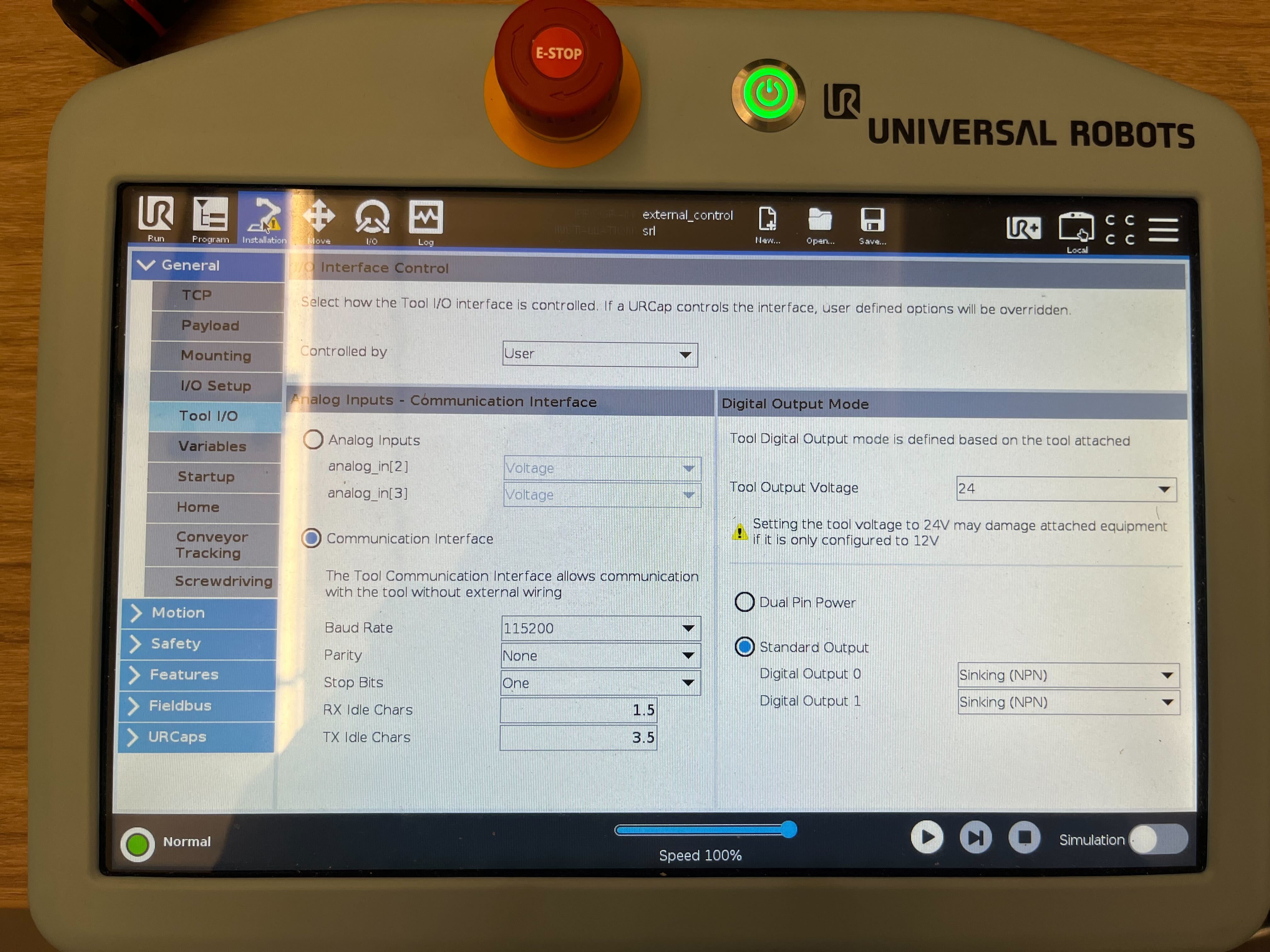
Configure Robotiq Gripper#
Before running the gear assembly or pick and place workflow, make sure to follow the instructions in setting up the
URrobot and the gripper.You will have to tweak the Tool I/O settings to
Usermode as shown below- especially if you see this error message:Failed to communicate with the Robotiq gripper
Note
If there are any issues with communication of the robot with the Jetson unit, refer to this section. Run the Driver and Hardware Tests to make sure your robot drivers are in a good state.
Set Up Cameras for Robot#
Connect your cameras:
If you are using RealSense cameras, connect them via USB 3. See available USB ports of the Jetson AGX Thor here. When connecting your RealSense cameras via USB, make sure to use a USB 3 port and cable.
It is recommended to use cables shorter than 3 m to guarantee stable transmission.
Place your stereo cameras such that their field of view fully covers the workspace that the robot arm will be operating in.
Camera Placement Guide: Object detection networks, as well as
nvblox, which is used for collision avoidance, are affected by the placement of cameras with respect to the workspace. Here we provide guidelines for placing cameras to achieve the best results. Deviation from these guidelines will degrade the quality of object detection and 3D reconstruction for obstacle avoidance. We recommend the following:Distance: Place cameras approximately 1 m from the bounds of the workspace.
Pitch: Locate cameras above the workspace surface such that they pitch down. We recommend 20 degrees, however pitches within the range of [10-30] are acceptable.
Multiple Cameras: For multiple cameras (currently a maximum of two are supported) we recommend that they view the workspace from significantly different viewing directions. In particular, we recommend that the yaw difference between the two cameras’ viewing angles around the world z-axis is greater than 90 degrees. Greater yaw and increased viewpoint differences between the cameras reduce occlusion in the scene. They also increase the quality and completeness of the 3D reconstruction being used for collision avoidance.
Decide on a name for your setup and substitute it for
<SETUP_NAME>in the instructions below.If your test setup includes multiple RealSense cameras identify their serial numbers using the command as shown below:
rs-enumerate-devices -SExample output:
Device Name                   Serial Number       Firmware Version
Intel RealSense D455          123456789123        5.16.0.1
Intel RealSense D455          123456789124        5.16.0.1
Intel RealSense D455          123456789125        5.16.0.1
Copy the unspecified.yaml file to a new file named
<SETUP_NAME>.yamlin the same folder and fill in the camera serial numbers.Follow Manipulator Camera Calibration instructions to calibrate the cameras with respect to the robot. The
calibration.launch.pyoutput from each calibration process will include a code snippet similar to the following example (values included for illustration only as they will differ for different setups):""" Static transform publisher acquired via MoveIt 2 hand-eye calibration """ """ EYE-TO-HAND: world -> camera """ from launch import LaunchDescription from launch_ros.actions import Node def generate_launch_description() -> LaunchDescription: nodes = [ Node( package="tf2_ros", executable="static_transform_publisher", output="log", arguments=[ "--frame-id", "world", "--child-frame-id", "camera", "--x", "1.77278", "--y", "0.939827", "--z", "-0.0753478", "--qx", "-0.128117", "--qy", "-0.0317539", "--qz", "0.955077", "--qw", "-0.265339", # "--roll", # "0.132507", # "--pitch", # "-0.229891", # "--yaw", # "-2.5843", ], ), ] return LaunchDescription(nodes)
In the static_transforms.launch.py file, duplicate the
hubble_test_benchitem in thecalibrations_dictdictionary and rename its key to<SETUP_NAME>.Update the transforms in the new
<SETUP_NAME>item with the calibrated pose values found in the calibration step above.Note
If installing from Debian, modify the
static_transforms.launch.pyfile found in/opt/ros/jazzy/share/isaac_ros_manipulation_bringup/launch/include/.Specifically, copy the calibrated values
--x tx,--y ty, and--z tzto the"translation": [tx, ty, tz]field, and the calibrated values--qx qx,qy qy,--qz qz, and--qw qwto the"rotation": [qx, qy, qz, qw]field.For example, adding a setup named
realsense_examplewith the calibrated values (for illustration only) from the previous point would look as follows:calibrations_dict = { 'hubble_test_bench': { 'world_to_camera': { 'parent_frame': 'world', 'child_frame': 'camera_1_link', 'translation': [-1.75433, -0.0887958, 0.419998], 'rotation': [-0.00447052, 0.138631, -0.0101076, 0.990282], # [qx, qy ,qz, qw] }, 'realsense_example': { 'world_to_camera': { 'parent_frame': 'world', 'child_frame': 'camera_1_link', 'translation': [1.77278, 0.939827, -0.0753478], 'rotation': [-0.128117, -0.0317539, 0.955077, -0.265339], # [qx, qy ,qz, qw] }, }, ...
Modify other appropriate values based on the tutorial:
Modify the
object_to_grasp_frametransform in the<SETUP_NAME>item of thecalibrations_dictdictionary in static_transforms.launch.py, to a desired grasp pose relative to the detected object. Feel free to leave this as the default for simplicity.Update the
world_to_target_frame_1andworld_to_target_frame_2transforms in the<SETUP_NAME>item of thecalibrations_dictdictionary in static_transforms.launch.py, to be two distinct poses that are reachable by the robot.Set the workspace bounds for nvblox:
Copy hubble_ur5e_test_bench.yaml to a new file named
<SETUP_NAME>.yamlin the same folder and update the workspace bound corners.Rebuild and source the
isaac_ros_manipulation_bringuppackage inside the Docker container:cd ${ISAAC_ROS_WS} && \ colcon build --symlink-install --packages-select isaac_ros_manipulation_bringup && \ source install/setup.bash
Copy hubble_ur5e_test_bench.yaml to a new file named
<SETUP_NAME>.yamlin/opt/ros/jazzy/share/isaac_ros_manipulation_bringup/config/nvblox/workspace_bounds/.How to choose the workspace bounds:
The workspace bounds define the space that is mapped for obstacle-aware planning and must cover the full space that the robot arm will be operating in.
The workspace min and max corners are defined in the nvblox
global_frameset here.The workspace bounds will be visualized when running the launch files (as a red bounding box). You can return to this step to adjust them after the system is running and producing visualizations.
A larger workspace will result in increased computational demands, which scale with the total number of voxels. The Isaac ROS Manipulation reference workflows have been tested on Jetson AGX Thor with workspace volumes of up to 8 m3 with 1 cm3 voxels. If a larger workspace is desired, the voxel size may be increased proportionally while keeping the total number of voxels fixed. The trade-off is that larger voxels may increase the likelihood of planning failures or increase motion time in scenarios that require the robot to move in tight proximity to obstacles.
Create a Manipulator Configuration File#
The manipulator configuration file defines the settings for both simulation and real-hardware operation in the Isaac ROS environment. One can use this file to change the camera type, workflow type and other parameters to suit different use cases.
The configuration file uses YAML format and can be created manually or generated using included configuration tools. Below are the key parameter groups and their descriptions:
Global Settings
camera_type: Type of camera being used (for example,REALSENSEorISAAC_SIM)num_cameras: Number of cameras to run for 3d reconstruction.workflow_type: Type of workflow to run (for example,PICK_AND_PLACE,POSE_TO_POSE,OBJECT_FOLLOWING)
Robot Hardware Settings
ur_type: Type of UR manipulator (for example,ur5eorur10e)gripper_type: Type of gripper attached (for example,robotiq_2f_85orrobotiq_2f_140)use_sim_time: Whether to use simulation time (trueorfalse)setup: The name of the setup you are running on (specifying calibration, workspace bounds and camera ids)robot_ip: Robot controller IP addresslog_level: Logging verbosity levelmoveit_collision_objects_scene_file: Path to a MoveIt scene file that defines static collision objects in the robot’s environment. These objects can represent tables, walls, or other static obstacles in the workspace that the robot needs to avoid during motion planning. The scene file can be created and exported from RViz’s MoveIt Motion Planning panel using the Scene Objects tab. Supported geometric primitives are boxes, spheres, and cylinders. The scene file is loaded at startup and the objects are added to the planning scene for collision avoidance.
Robot Description Parameters
urdf_path: Path to robot/gripper URDF filesrdf_path: Path to semantic robot description filejoint_limits_file_path: Joint limits configuration filekinematics_file_path: Robot kinematics configurationmoveit_controllers_file_path: MoveIt controllers configurationros2_controllers_file_path: ROS 2 controllers configurationcontroller_spawner_timeout: Controller initialization timeout (seconds)tf_prefix: Prefix for TF framesruntime_config_package: Package with runtime configurationsinitial_joint_controller: Primary joint controller name
cuMotion specific Parameters
cumotion_urdf_file_path: Path to the cuMotion-specific URDF filecumotion_xrdf_file_path: Path to the cuMotion-specific XRDF filedistance_threshold: Proximity threshold (in meters) for collision checksenable_nvblox: Enable/disable nvblox for 3D scene reconstruction and dynamic collision avoidance (trueorfalse)
Note
Choosing cuMotion URDF and XRDF files: The URDF and XRDF files to use depend on the workflow type:
For Object Following and Pose-to-Pose workflows, use the vanilla robot description files (without a tool), for example
ur5e.urdf/ur5e.xrdforur10e.urdf/ur10e.xrdf.For Pick and Place and Gear Assembly workflows, use the robot+gripper description files, for example
ur5e_robotiq_2f_140.urdf/ur5e_robotiq_2f_140.xrdf.
All files are available in the
sharedirectory of theisaac_ros_cumotion_robot_descriptionpackage.Time Synchronization Parameters
time_sync_slop: The time in seconds nodes keep as sync threshold to sync images and joint states. If one has a slower machine, tweaking this variable is useful to get syncs but at the cost of accuracy. If the slop parameter is too high, the robot will sync with older images or joint states leading to incorrect depth segmentation
Perception Parameters
depth_type: Stereo disparity engine mode (choices includeESS_FULL,ESS_LIGHT,FOUNDATIONSTEREO,ISAAC_SIM,REALSENSE)ess_engine_file_path: Path to ESS engine binaryenable_dnn_depth_in_realsense: Enable/disable DNN stereo depth estimation for RealSense cameras (trueorfalse)pose_estimation_type: Method for pose estimation (choices includeFOUNDATION_POSEorDOPE)pose_estimation_input_qos: Quality of Service for pose estimation inputpose_estimation_input_fps: Input frame rate for pose estimationpose_estimation_dropped_fps: Expected frame rate after message dropsdope_engine_file_path: Path to DOPE engine filedope_model_file_path: Path to DOPE model (ONNX format)foundation_pose_mesh_file_path: Mesh file for pose estimation via FoundationPosefoundation_pose_refine_engine_file_path: Engine file for refining pose estimationfoundation_pose_texture_path: Texture file for pose estimation via FoundationPosefoundation_pose_score_engine_file_path: Engine file for scoring pose qualityobject_detection_type: Type of object detection method (choices includeGROUNDING_DINO,RTDETR,SEGMENT_ANYTHING, orSEGMENT_ANYTHING2)grounding_dino_confidence_threshold: Confidence threshold for Grounding DINO detectionsgrounding_dino_default_prompt: Default text prompt for Grounding DINO object detectiongrounding_dino_engine_file_path: Path to Grounding DINO engine filegrounding_dino_model_file_path: Path to Grounding DINO model (ONNX format)grounding_dino_network_image_height: Network input image height for Grounding DINOgrounding_dino_network_image_width: Network input image width for Grounding DINOrtdetr_engine_file_path: Engine file for RT-DETR object detectionobject_class_id: Class ID of the object to be detected. The default corresponds to the Mac and Cheese box if the SyntheticaDETR v1.0.0 model file is used. Refer to the SyntheticaDETR model documentation for additional supported objects and their class IDs.rt_detr_confidence_threshold: Confidence threshold for RT-DETR detectionssam_model_repository_paths: list of paths to Segment Anything Triton model repositories (for example,${ISAAC_ROS_WS}/isaac_ros_assets/models/triton)sam2_model_repository_paths: list of paths to Segment Anything 2 Triton model repositories (for example,${ISAAC_ROS_WS}/isaac_ros_assets/models/triton)segment_anything_input_detections_topic: topic name for segment anything input detectionssegment_anything_input_points_topic: topic name for segment anything input pointssegment_anything2_input_points_topic: topic name for segment anything 2 input pointssegmentation_type: type of segmentation method (choices includeNONE,SEGMENT_ANYTHING, orSEGMENT_ANYTHING2)
Pick and Place Parameters
use_ground_truth_pose_in_sim: Whether to use ground truth pose in simulation (trueorfalse)pick_and_place_planner_retries: Number of retries for the planning algorithmpick_and_place_retry_wait_time: Wait time (in seconds) between planning retriessim_gt_asset_frame_id: Ground truth asset frame identifier in simulationgrasps_file_path: Path to the file containing predefined grasp configurationstime_dilation_factor: Factor to control the simulation speed of the robotmove_to_home_pose_after_place: Flag to move the robot to the home pose after placing the object (trueorfalse). This can be used for automated testing.home_pose: List of joint values for the home poseuse_pose_from_rviz: When enabled, the end effector interactive marker is used to set the place pose through RViz (trueorfalse).selection_policy: Object selection policy to filter the output poses from the pose estimation backend (choices includeHIGHEST_SCORE,FIRST, orRANDOM)
Object Attachment Parameters
object_attachment_type: Shape of the attachment geometry (SPHERE,CUBOID, orCUSTOM_MESH)object_attachment_scale: Dimensions of the attachment geometry (list of floats)attach_object_mesh_file_path: Path to the object visualization meshend_effector_mesh_resource_uri: URI for the end effector mesh resource
Visualization Options
enable_rviz_visualization: Enable or disable RViz visualization (trueorfalse)enable_foxglove_visualization: Enable or disable Foxglove Studio visualization (trueorfalse)rviz_config_file: Path to the RViz configuration file
Performance and Profiling Settings
enable_cuda_mps: Enable CUDA Multi-Process Service (trueorfalse)cuda_mps_pipe_directory: Directory for CUDA MPS pipesenable_nsight_profiling: Enable Nsight profiling (trueorfalse)nsight_profile_duration: Duration of Nsight profiling session (in seconds)delay_to_start_nsight: Delay (in seconds) before beginning Nsight profiling. This provides time for systems to stabilize prior to profiling.nsight_profile_output_file_path: File path where the Nsight profiling results will be saved.enable_system_wide_profiling: Enable system-wide profiling (trueorfalse)
Gear Assembly Parameters
gear_assembly_model_path: Path to the gear assembly modelgear_assembly_model_file_name: Name of the gear assembly model filegear_assembly_policy_alpha: Alpha value for the gear assembly policygear_assembly_observation_topic: Topic name for the gear assembly observationgear_assembly_joint_state_topic: Topic name for the gear assembly joint statesgear_assembly_target_joint_state_topic: Topic name for the gear assembly target joint statesgear_assembly_target_tcp_state_topic: Topic name for the gear assembly target TCP statesgear_assembly_gear_insertion_request_topic: Topic name for the gear assembly gear insertion requestgear_assembly_goal_pose_topic: Topic name for the gear assembly goal posegear_assembly_gear_insertion_status_topic: Topic name for the gear assembly gear insertion statusgear_assembly_ros_bag_folder_path: Path to the gear assembly ROS bag foldergear_assembly_enable_recording: Enable recording of the gear assembly ROS baggear_assembly_use_joint_state_planner: Use joint state planner for gear assembly (trueorfalse)gear_assembly_peg_stand_mesh_file_path: Path to the peg stand mesh filegear_assembly_gear_large_mesh_file_path: Path to the gear large mesh filegear_assembly_gear_small_mesh_file_path: Path to the gear small mesh filegear_assembly_gear_medium_mesh_file_path: Path to the gear medium mesh filegear_assembly_use_ground_truth_pose_in_sim: Use ground truth pose in simulation (trueorfalse)gear_assembly_verify_pose_estimation_accuracy: Verify pose estimation accuracy (trueorfalse)gear_assembly_run_rl_inference: Run RL inference (trueorfalse)gear_assembly_output_dir: Output directory for the gear assembly
Additional MPS Parameters
cuda_mps_client_priority_container: Client priority for container tasks in MPScuda_mps_client_priority_robot_segmenter: Client priority for robot segmentation tasks in MPScuda_mps_active_thread_percentage_robot_segmenter: Active thread percentage for robot segmentation in MPScuda_mps_client_priority_planner: Client priority for the cuMotion planner in MPScuda_mps_active_thread_percentage_planner: Active thread percentage for the cuMotion planner in MPScuda_mps_active_thread_percentage_container: Percentage of active threads reserved for container tasks when CUDA Multi-Process Service (MPS) is enabled
For a complete example configuration, see the sample files in the params directory.
To verify that you have setup the Isaac ROS Manipulation correctly, run the following command:
export ENABLE_MANIPULATOR_TESTING=on_robot
export ISAAC_ROS_MANIPULATION_TEST_CONFIG=<config_file_path_for_your_robot>
python3 -m pytest ${ISAAC_ROS_WS}/src/isaac_ros_manipulation/isaac_ros_manipulation_bringup/test
Note
You can also use colcon test --packages-select isaac_ros_manipulation_bringup to run the tests.
However, pytest has a better output and makes it easier to view status and progress of the tests.
If these tests fail, review Isaac ROS Manipulation Testing Guide for more information.
It is recommended to run the tests manually using launch_test and then manually inspecting the results.
This will run a series of tests to verify that the Isaac ROS Manipulation is working correctly.
Why does my UR robot driver not launch correctly ?#
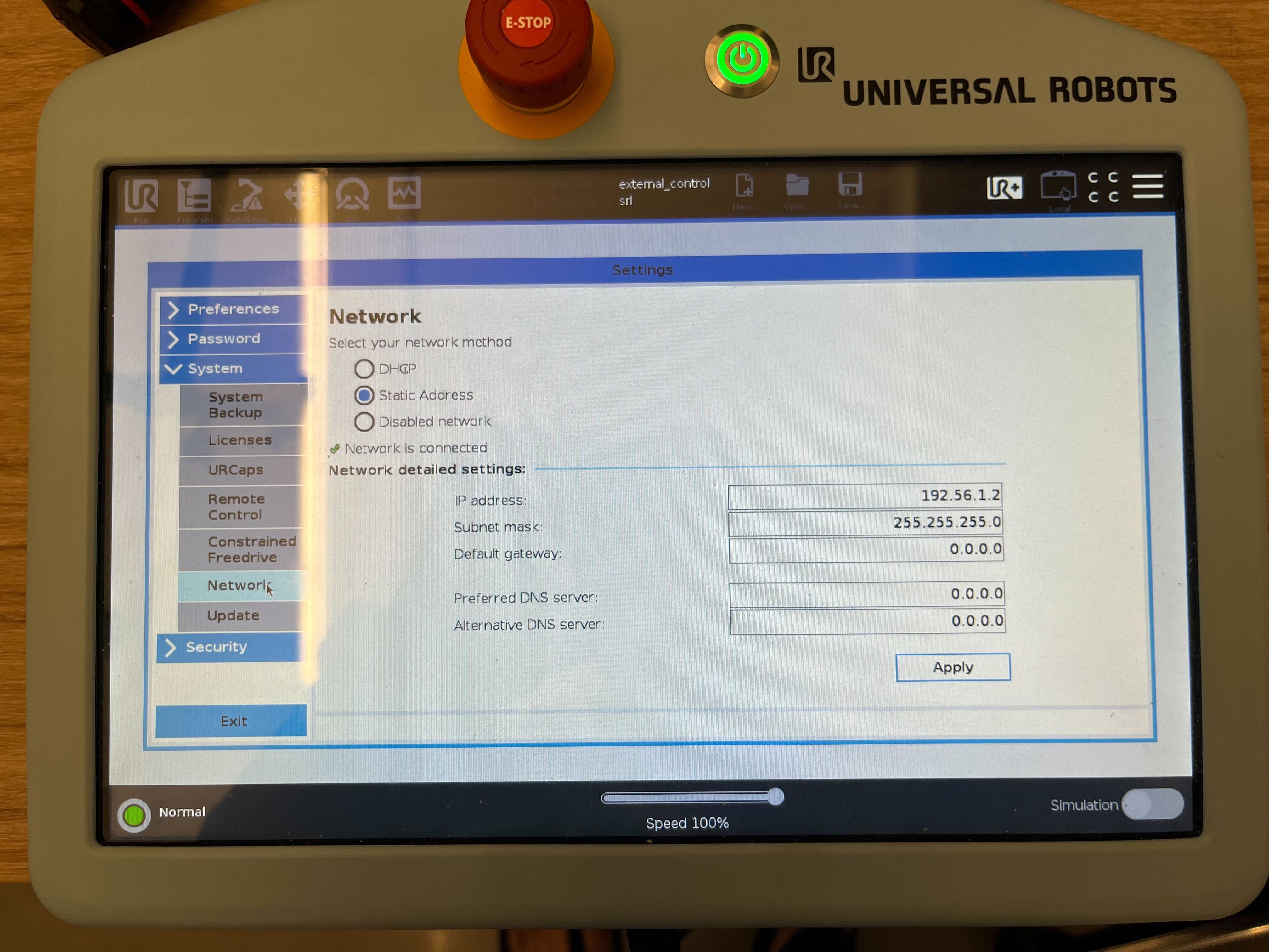
There can be several reasons but a lot of them can pertain to poor networking setup.
Make sure
192.56.1.2and192.56.1.1are ping-able from your Jetson machine.Make sure the Ethernet connection is set up correctly.
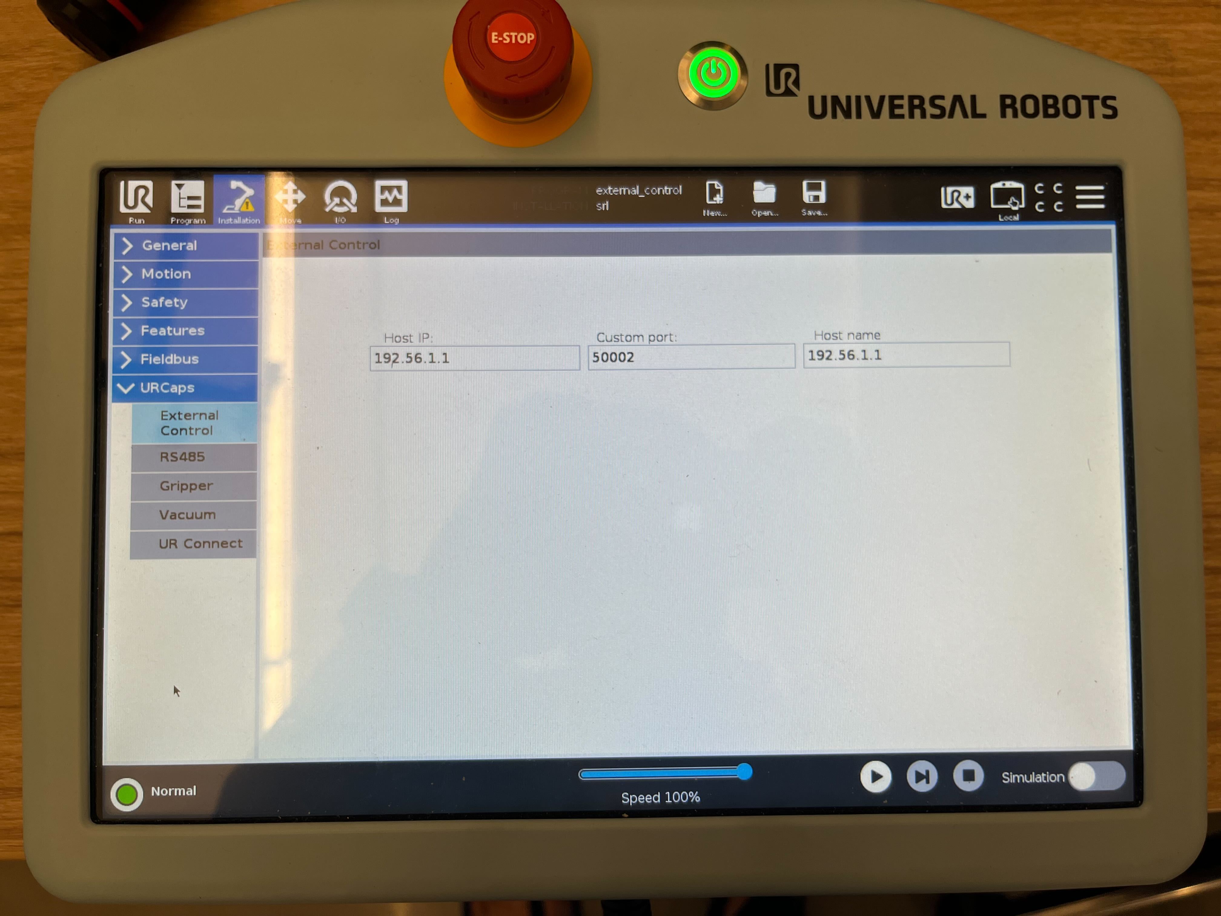
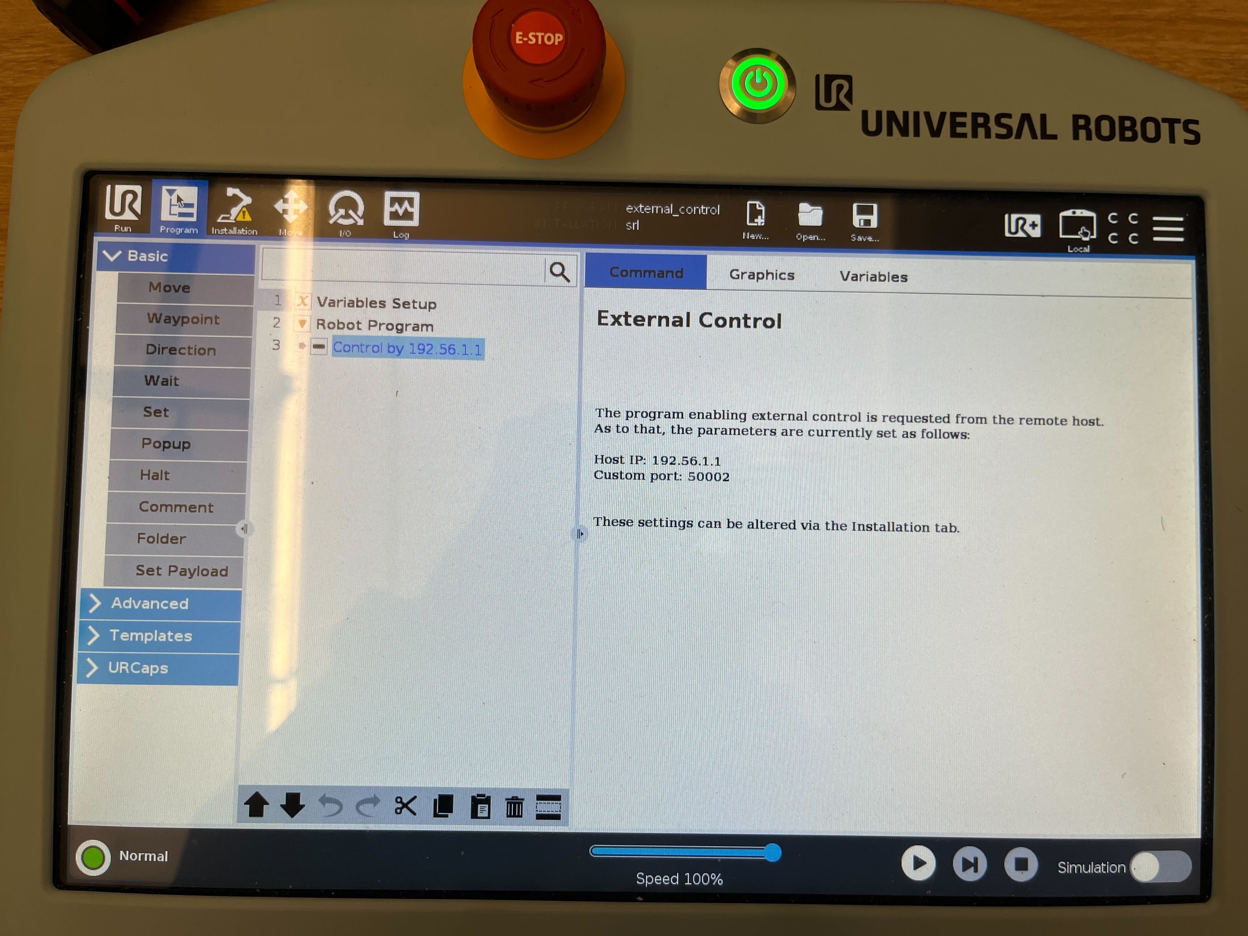
Make sure you have setup External control correctly as shown in the figure below.
Make sure you have setup the Robotiq Gripper up correctly and pointed it to
Usermode.
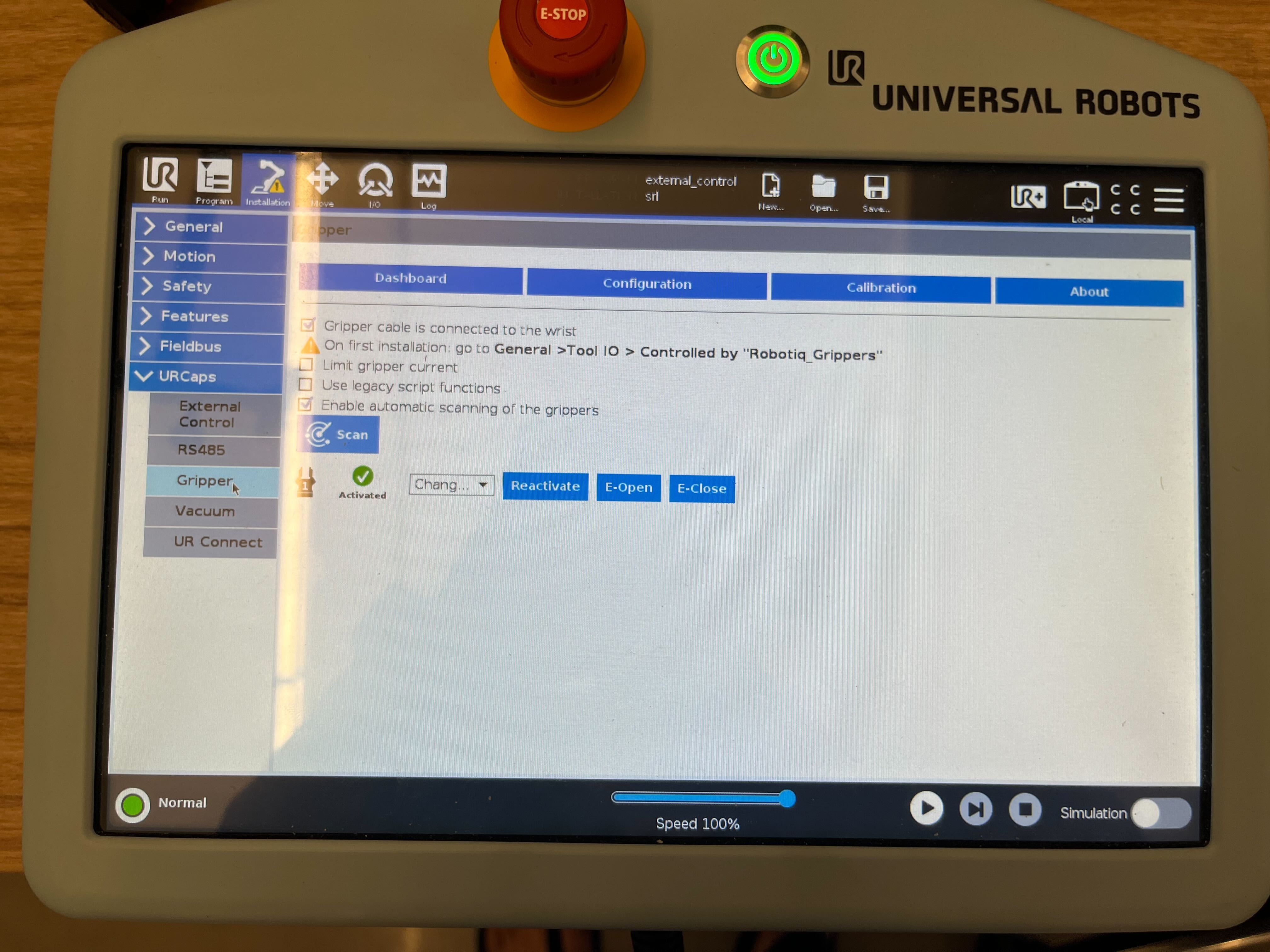
Make sure after setting up URCaps and doing the above step you can control the gripper using the open and close buttons as shown below.
Make sure you have setup the program correctly to External control as shown below.
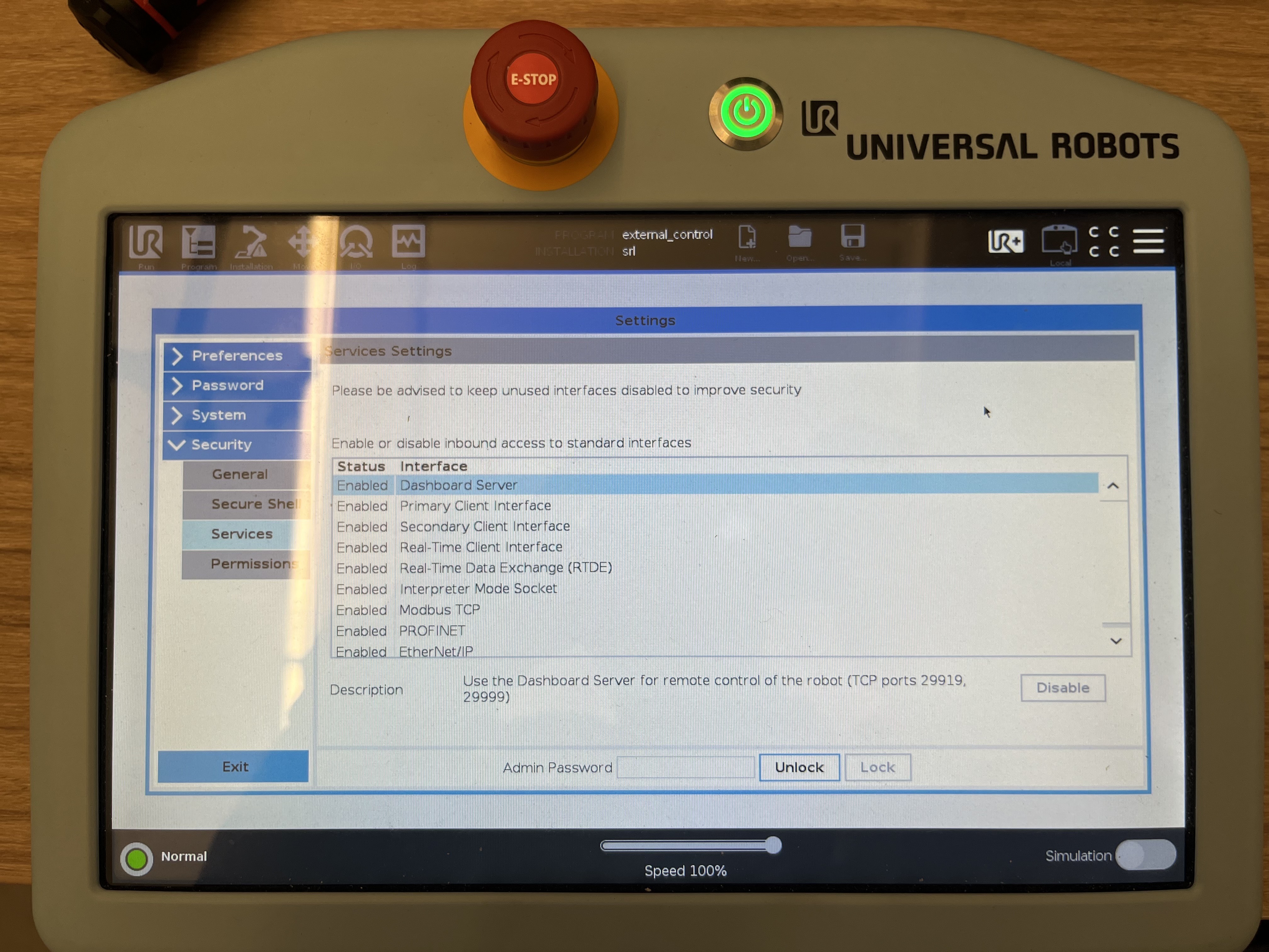
Make sure you have given all the permissions required for the Jetson compute box to communicate with the robot.
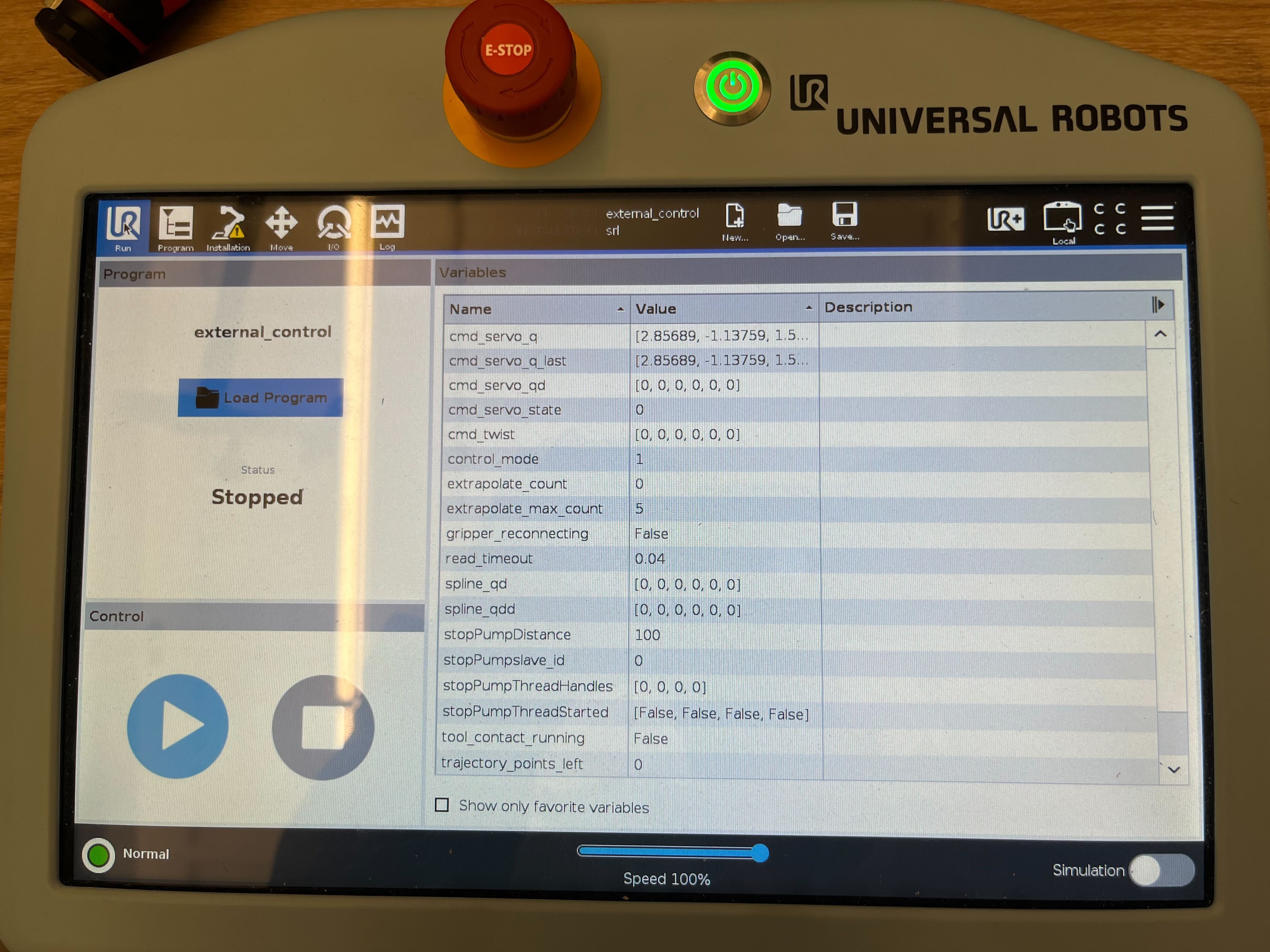
Before running the drivers, make sure your
Runscreen looks like this.
If you are still facing issues, refer to the Isaac ROS Manipulation Testing Guide for more information.