NVIDIA Isaac Perceptor Reference Architecture
This document presents a validated reference architecture for Isaac Perceptor that provides a robust foundation for developing end-use case applications. Alongside this tested architecture, several customizable variations are demonstrated to illustrate how Isaac Perceptor integrations can be tailored to meet diverse application requirements. Although these variations have not been SQA tested, they exemplify the flexibility and potential of Isaac Perceptor.
What is NVIDIA Isaac Perceptor?
Isaac Perceptor is a vision-based 3D perception solution designed for mobile robots. While Autonomous Mobile Robots (AMRs) excel in structured environments, they often struggle to navigate unstructured and human-centric environments, commonly known as ‘brownfield sites’. Isaac Perceptor overcomes these challenges by offering comprehensive 3D surround perception through multi-camera AI-based depth perception, visual odometry, and real-time 3D voxel occupancy map generation. Isaac Perceptor also includes robust semantics awareness for safer operation and collaboration with human workers in dynamic environments.
What is this document?
This document demonstrates the integration of various components of Isaac Perceptor into a comprehensive end-to-end 3D perception solution. It includes a validated reference architecture that is confirmed to function effectively. Beyond the tested reference architecture, we present additional variations that showcase how Isaac Perceptor can be customized to meet the requirements of downstream applications. While these variations have not undergone SQA testing, they exemplify the potential capabilities of Isaac Perceptor.
Who is this document for?
This document is to assist engineers in the Autonomous Mobile Robot (AMR) ecosystem, including those at Original Equipment Manufacturers (OEMs), freight service providers, and independent software vendors (ISVs). It provides guidance on utilizing the reference architecture as a foundational starting point to develop robust visual AI-based perception solutions for any mobile robot.
Reference Architecture
The reference architecture for Isaac Perceptor comprises the following components.
Visual Input: Generates RGB and depth images using NVIDIA Hawk Camera.
Possible Variations: Utilization of different RGB or RGBD cameras.
Visual Odometry: Consumes RGB images to produce camera poses.
Possible Variations: Various odometry & localization methods.
Semantic Segmentation: Processes RGB images to generate segmentation masks.
Voxel Grid Mapping: Integrates RGB images, depth images, camera poses, and segmentation masks to create 3D voxel grid maps and 2D cost maps.
Planning and Navigation: Utilizes 2D/3D cost maps to generate robot control.
Visualization: Aggregates outputs from all components to produce visual representations of camera images, poses, and voxel grid maps.
Hardware Platform: Consists of edge devices and developer kits for running Isaac Perceptor.
Possible Variations: Integration of additional devices for specific tasks.
This architecture is illustrated in the following diagram:
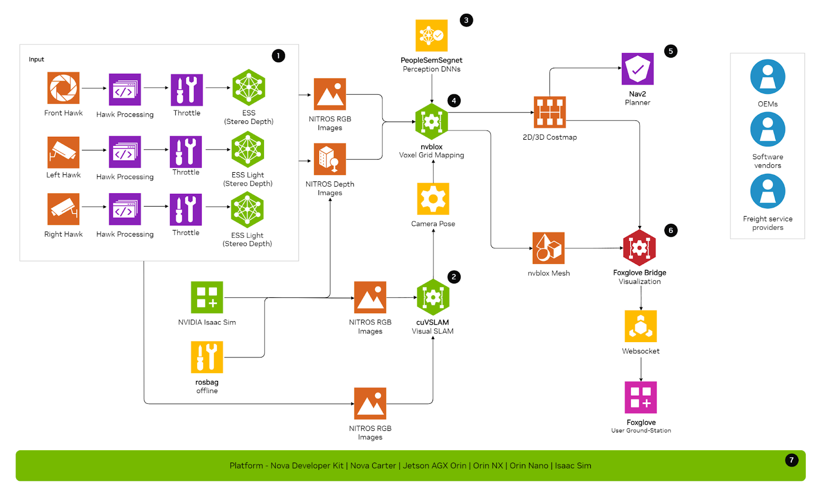
The components in the reference architecture represent functional blocks that can have multiple implementations. The primary implementation for each component has undergone testing by NVIDIA. For certain components, we provide alternative implementations later in the document to demonstrate how the reference architecture can be tailored for specific downstream applications.
Components
This section details the components used in Isaac Perceptor and provides links to possible variations that can be made to the default architecture to accommodate different use cases. In the Variations section, we offer tutorials and resources as a starting point for implementing these variations on your specific setup.
Visual Input
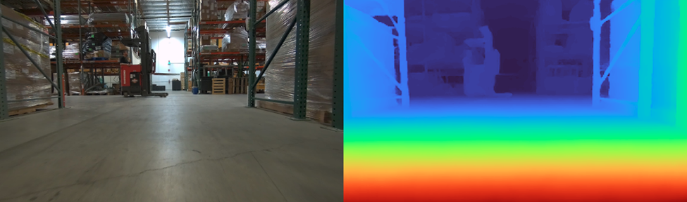
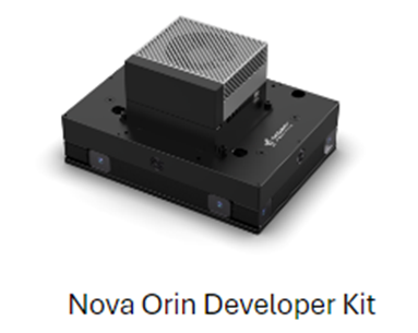
This component is responsible for supplying the RGB and depth images required by other components. Specifically, RGB images are utilized by the Visual Odometry (2), Voxel Grid Mapping (4), and Semantic Segmentation (3) components. Depth images are essential for the Voxel Grid Mapping (4) component. In the featured architecture, this component is implemented using three HAWK stereo cameras for capturing RGB images. This camera configuration is identical to that included in the Nova Orin Developer Kit. The RGB images provided by these cameras are processed by the ESS Depth Estimation model, which generates the depth images required for voxel grid mapping.
For more information, see:
Isaac Perceptor can also be utilized with the following input sources:
Rosbag: Perceptor is compatible with pre-recorded data in rosbags.
For example, Run Isaac ROS Nvblox with a rosbag.
Isaac Sim: Perceptor works with input from simulated environments in Isaac Sim. Refer to the example below. This tutorial demonstrates how to reconstruct a simulated scene and generate a 2D costmap, which is then used with Nav2 for navigation. Detailed hardware requirements and prerequisites are provided in the tutorial.
For example, Run Isaac ROS NvBlox with Isaac Sim.
Variations:
Use Alternate RGB Cameras
While the default reference architecture uses three Hawk cameras for processing, this is not a strict requirement.
cuVSLAM can ingest RGB images from various multi-camera configurations, provided that the intrinsics and relative extrinsics of the cameras are known. cuVSLAM requires synchronized images when using multiple cameras. If different RGB cameras are used, synchronization must be ensured so that ROS image messages sent to the Isaac ROS Visual SLAM node have synchronized timestamps. Besides odometry, Nvblox additionally requires depth images as input. The reference architecture uses the ESS model for depth generation. If using a different RGB camera, ensure that the input requirements for ESS are met, as outlined in the API documentation.
For more information, see Isaac ROS ESS API Documentation.
Use Zed X
Contact Stereolabs for their integration of Zed X Camera with Isaac Perceptor.
Use RGBD Cameras
This variation corresponds to Visual Input.
In the reference architecture, we use stereo RGB cameras and rely on neural networks (that is, ESS DNN) to estimate depth information. The alternative is to use RGBD cameras. Additionally, use of RGBD cameras can free up computational resources on hardware platforms like Jetson Orin.
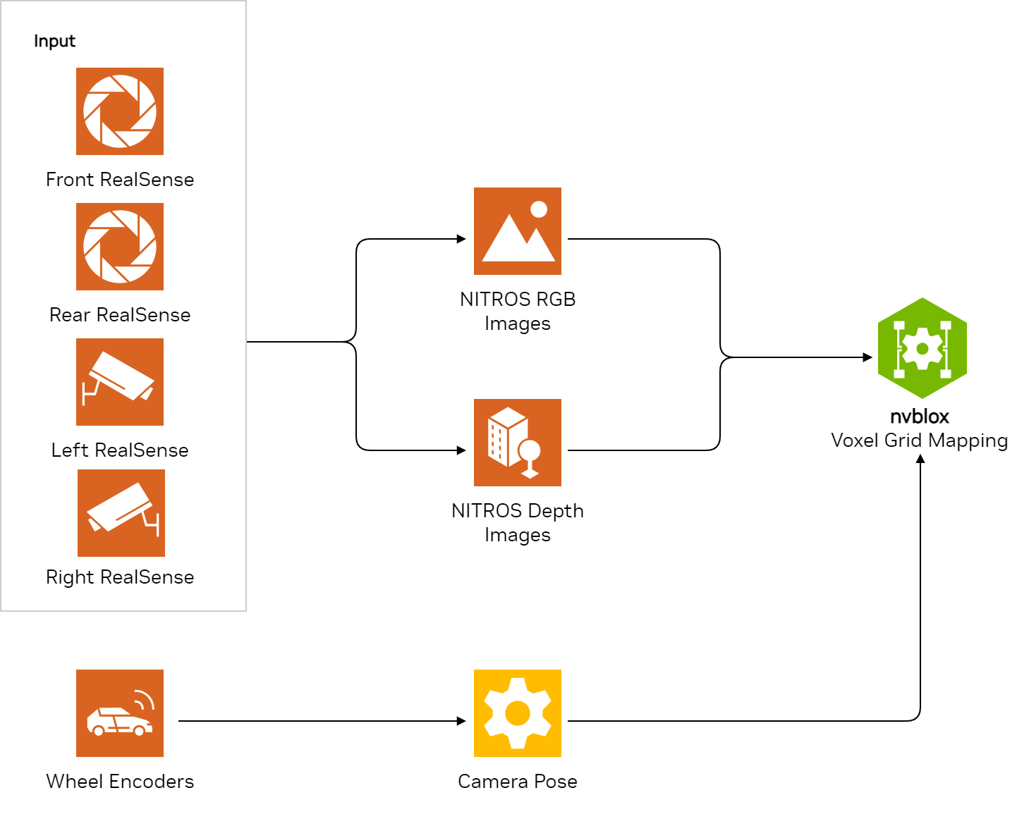
In this variation, we eliminate depth processing (on Jetson Orin) entirely by using RGBD cameras. This configuration still provides the required information for components such as cuVSLAM (that is, RGB image) and Nvblox (that is, depth image). Here is a list of RGBD cameras along with pointers on how to integrate them with Isaac Perceptor:
Intel RealSense: You can run Isaac ROS Nvblox in single camera mode using a RealSense camera. Follow the tutorial on either live data or recorded data.
For more information, see RealSense camera and List of supported Realsense cameras.
For example, Tutorial: Running with a RealSense camera (live or from recorded data).
Orbbec: Orbbec’s Gemini 330 series Stereo Vision 3D cameras have been integrated with Perceptor components, specifically Isaac ROS Visual SLAM and Nvblox, on Jetson Orin. Depth computation is handled by Orbbec’s latest depth engine ASIC, which reduces the computational load on the Jetson Orin.
Read more in the Orbbec PR. For more information about this integration, reach out to Orbbec or contact NVIDIA for details, also see:
LIPS: The LIPSedge 3D AE470 camera is supported within the Perceptor workflow, specifically with Nvblox, in single-camera mode.
Read more in the LIPS PR. For more information about this integration, reach out to LIPS or contact NVIDIA for details.
Visual Odometry
This component processes the multi-camera RGB images to estimate the pose of the cameras as they move through the environment. These camera poses are essential for Voxel Grid Mapping (4) and Navigation (5).
In the featured architecture, this component is implemented using cuVSLAM, NVIDIA’s accelerated VSLAM library. When provided with multiple time-synchronized RGB images, cuVSLAM accurately generates odometry.
Using multiple cameras enhances the robustness of the solution, particularly in featureless environments. cuVSLAM supports up to 16 stereo cameras. Technical details and tutorials can be found in the Isaac Documentation for cuVSLAM.
For more information, see cuVSLAM (CUDA Accelerated VSLAM Library).
Variations:
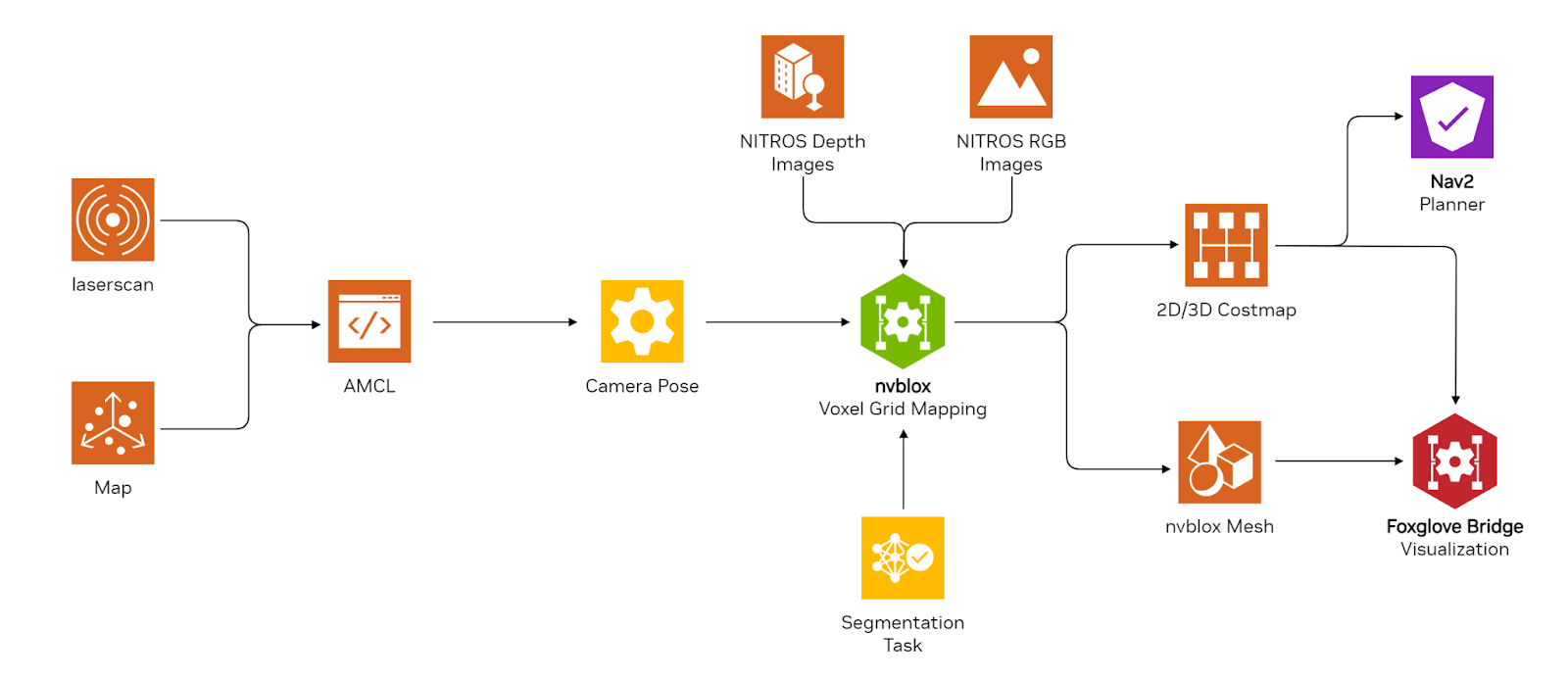
Use a Different Odometry Source and Localization Method
The reference architecture offers a reference integration with the Nav2 stack, utilizing cuVSLAM for odometry. While the future default architecture will employ the cuVSLAM library for localization (camera pose estimation), there may be scenarios where alternative odometry and localization techniques are preferred. This flexibility allows for the integration of a localization scheme optimized for specific environments.
AMCL: When a static map of the robot’s environment is available, cuVSLAM can be replaced with AMCL, which uses the static map for localizing the robot. For detailed guidance, Run Isaac ROS NvBlox with Isaac Sim Autonomous Navigation with Isaac Perceptor and Nav2. The tutorial includes steps on creating a map of your environment using lidar on the robot.
Wheel Odometry and IMU with AMCL: cuVSLAM for odometry can be substituted with wheel odometry and IMU data. Localization information would be derived from the sensors on the robot’s wheel motors and IMU. Initially, AMCL would be required to create a static map of the environment if one is not already available. Additionally, AMCL is essential for correcting odometry drift. This variation employs AMCL for global localization and wheel odometry for local positioning. For example, Visual SLAM using a RealSense camera with integrated IMU.
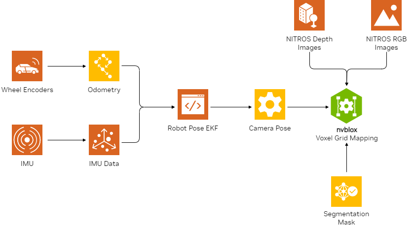
If your system uses multiple sensors including camera, lidar, IMU, and more, we recommend using the Isaac ROS Correlated Timestamp Driver. This provides functionality for accurate acquisition time of sensor data translated to system time, which enables perception while using multiple sensors.
For more information, see Isaac ROS Correlated Timestamp Driver.
Semantic Segmentation
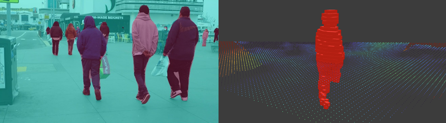
This component processes the RGB images provided by the Visual Input (1) and generates segmentation maps used by Voxel Grid Mapping (4). These segmentation masks add meaningful semantics to the voxel grid maps, allowing for improved handling of dynamic obstacles in the environment and enabling the robot to modify its behavior based on the identified semantics.
In the featured architecture, this component is implemented using the PeopleSemSegNet segmentation model. The segmentation masks generated by this model create an additional layer in the voxel grid map specifically for identifying and tracking people. For more information, see PeopleSemSegNet.
Voxel Grid Mapping
This core component is responsible for integrating RGB, depth, pose, and more to build an occupancy map, which is essential for navigation.
In the featured architecture, this component is implemented using Nvblox. Nvblox processes RGB images, depth images, segmentation masks, and camera poses produced by the other components to generate one or more occupancy masks, with optional colors for visualization. The costmap produced is utilized by the Navigation component (5) to identify safe areas for the robot to travel, while the RGB colors may be used for Visualization (6). For more information, see Nvblox.
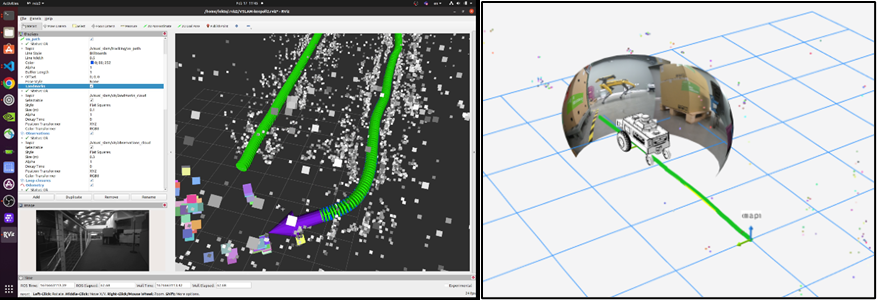
Visualization
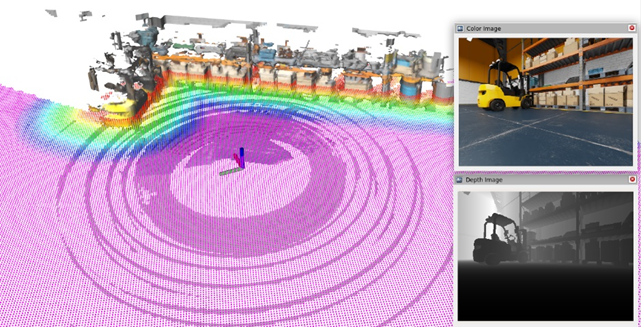
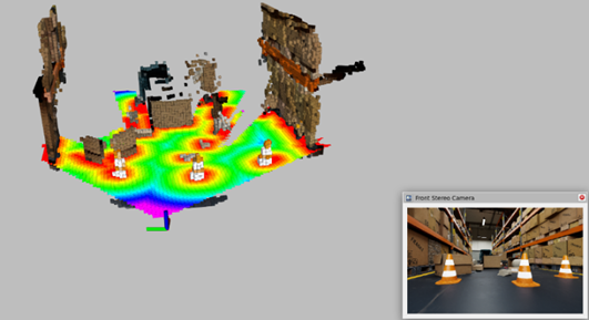
This component is useful for debugging purposes, such as visualizing the environment for collision avoidance and motion planning. It also aids in capturing the environment in digital form for visualization and understanding by engineers and developers.
For example, Nvblox generates a colorized 3D reconstruction of the environment for visualization. It also provides plugins to visualize this mesh in RViz and Foxglove, with real-time updates as the mesh is built.
For more information, see Foxglove.
Hardware Platforms
This component encompasses the hardware platforms on which Isaac Perceptor operates and has been tested. Isaac Perceptor has been tested on the following platforms:
Nova Orin Developer Kit (includes Jetson AGX Orin) |
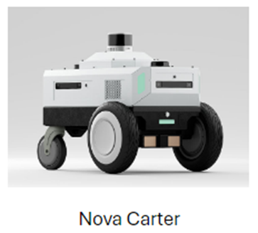
Nova Carter (includes Jetson AGX Orin) |
|---|---|
|
|
For more information, see:
Nova Carter Reference Robot
For example:
Tutorial: Isaac Perceptor with Nova Carter
Variations:
Use Additional Devices for Specific Tasks
The perception-related tasks in the current reference architecture are executed entirely on a single NVIDIA Jetson AGX Orin. Given the numerous processing nodes involved, this architecture consumes substantial computing and memory resources.
For navigation purposes, it is recommended to run a navigation stack like Nav2 on an additional Jetson AGX Orin or an x86 system to ensure optimal performance. For instance, if you have an existing Lidar-based SLAM navigation stack running on an x86 system, you can integrate this with Isaac Perceptor for perception capability.
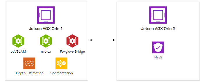
In this variation, besides running a navigation stack, you can execute additional tasks such as Large Language Models (LLMs) or Vision-Language Models (VLMs) on the x86 system or on an additional Jetson AGX Orin.
NVIDIA provides a sample config for the Carter robot using Cyclone DDS below. If you are using a Carter robot, add this profile to carter-dev/docker/middleware_profiles:
<CycloneDDS xmlns="https://cdds.io/config" xmlns:xsi="http://www.w3.org/2001/XMLSchema-instance" xsi:schemaLocation="https://cdds.io/config https://raw.githubusercontent.com/eclipse-cyclonedds/cyclonedds/master/etc/cyclonedds.xsd">
<Domain id="any">
  <General>
  <Interfaces>
   <NetworkInterface name="eth0"  multicast="false" />
  </Interfaces>
  <AllowMulticast>false</AllowMulticast>
  <EnableMulticastLoopback>false</EnableMulticastLoopback>
 </General>

 <Discovery>
 <!-- Replace ips with robot and visualization machine ip -->
  <Peers>
    <Peer address="192.168.1.100"/>
   <Peer address="192.168.1.101"/>
  </Peers>
  <ParticipantIndex>auto</ParticipantIndex>
  <MaxAutoParticipantIndex>200</MaxAutoParticipantIndex>
 </Discovery>
</Domain>
</CycloneDDS>
Add the following line to carter-dev/docker/Dockerfile.carter_dev:
ENV CYCLONEDDS_URI=/usr/local/share/middleware_profiles/cyclone_unicast_profile.xml
Ensure all devices are connected to the same local robot network by setting the same ROS domain ID on them. Test that ROS can communicate across all devices by running a test node on one, and echoing topics on the others.
For more information, see ROS Domain ID.
For instance, if you are testing this on a Carter robot with an additional Jetson device, you can run perception and visualization on the Jetson (see command 1 below) and navigation on the Carter robot with 3D lidar disabled (see command 2 below).
Command 1
ros2 launch nova_developer_kit_bringup perceptor.launch.py stereo_camera_configuration:=front_left_right_configuration use_foxglove_whitelist:=False
Command 2
ros2 launch nova_carter_bringup navigation.launch.py enable_navigation:=True enable_nvblox_costmap:=True stereo_camera_configuration:=no_cameras enable_3d_lidar_costmap:=False enabled_2d_lidars:='front_2d_lidar,back_2d_lidar' enable_2d_lidar_costmap:=True enable_wheel_odometry:=True run_foxglove:=False enable_global_navigation:=True map_yaml_path:=<absolute-path-to-map-yaml-file> enable_3d_lidar_localization:=False
Additional Resources
To get started using Isaac Perceptor with your mobile robots, you can check out our expanding collection of resources.
Learn more about featured NVIDIA solutions:
cuVSLAM (CUDA Stereo Visual SLAM)
Review Documentation and Samples: