2. Definitions
Acronyms
AGV |
Automated Guided Vehicle |
API |
Application Programming Interface |
AMR |
Autonomous Mobile Robot |
FOV |
Field of View |
GMSL |
Gigabit Multimedia Serial Link communication protocol used for video distribution |
HFOV |
Horizontal FOV |
HW |
Hardware |
I2C |
Inter-Integrated Circuit serial communication protocol |
ROS |
Robot Operating System |
SDK |
Software Development Kit |
SoC |
System on Chip |
SW |
Software |
URDF |
Unified Robotics Description Format |
VFOV |
Vertical FOV |
2.1. Coordinate Systems
2.1.1. AMR Coordinate System
Coordinates Orientation
The AMR employs a Right Handed Coordinate System. The AMR forward direction is aligned with the positive X direction.
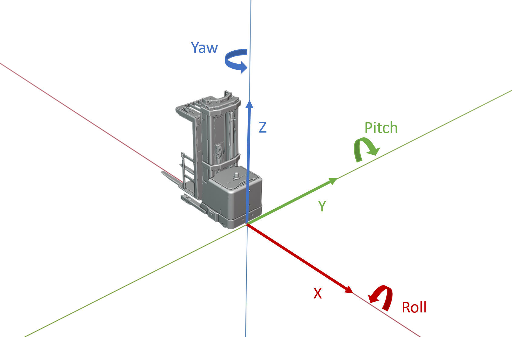
X Direction
X positive points to the AMR front direction, X is parallel to the ground in typical AMR conditions.
Y Direction
Y positive points to the AMR left direction, Y is parallel to the ground in typical AMR conditions.
Z Direction
Z positive points to the AMR up direction, Z is perpendicular to the ground in typical AMR conditions.
Coordinates Origin
The coordinates origin or vertex is fixed to the AMR body at the foremost AMR surface on X Direction, center of the body width on Y Direction, and ground surface on the Z Direction in typical AMR conditions.
Roll Direction
Roll positive is the direction rotating Y Direction for 90 degrees to fully align with Z Direction.
Pitch Direction
Pitch positive is the direction rotating Z Direction for 90 degrees to fully align with X Direction.
Yaw Direction
Yaw positive is the direction rotating X Direction for 90 degrees to fully align with Y Direction.
Roll Range
Roll range is (-180,180] in degree.
Pitch Range
Pitch range is [-90,90] in degree.
Yaw Range
Yaw range is (-180,180] in degree.
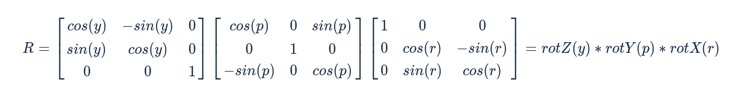
Rotation
Sub-linked parts in AMR Coordinate System have global extrinsic rotations in the order of Roll Direction, Pitch Direction and Yaw Direction.
The rotation matrix R is defined as following, r is Roll in degree, p is Pitch in degree and y is Yaw in degree.
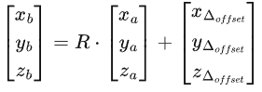
Linear Translation
Linear translation applies to sub-linked parts after Rotation.
For example, a sub-linked stereo camera has xΔoffset, yΔoffset, zΔoffset (from Coordinates Origin to stereo-camera Vertex) as linear translation and R as the Rotation matrix in AMR Coordinate System. A detected point [x:sub:a, ya, za] from the perspective of the stereo camera has its position at [x:sub:b, yb, zb] from the perspective of the Vehicle Coordinate System.