Isaac for Manipulation Camera Calibration#
These instructions are for extrinsic calibration of a RealSense camera with a robot manipulator. This procedure has been tested with Flexiv Rizon 4s. For dual-camera setups, follow the Calibration Procedure twice (once for each camera), with only one camera plugged into the system each time.
Calibration Target#
Supported Patterns#
This tutorial supports both ArUco and ChArUco calibration targets. For best results, use a ChArUco pattern with an odd number of rows and a high number of markers. Print it on the largest board that suits the robot you are calibrating.
This tutorial supports the following ArUco pattern dictionaries:
DICT_4X4_250DICT_5X5_250DICT_6X6_250DICT_7X7_250DICT_ARUCO_ORIGINAL
Target Printing#
The calibration targets must be rigid without any noticeable bending when flat and during operation. Use an aluminum and low-density polyethylene (LDPE) composite for the required flatness and stiffness.
Note
Use calib.io to obtain high-quality calibration targets. This tutorial uses targets purchased from calib.io.
If printing from a different source, ensure that the printed targets are:
Non-glossy to minimize light reflections and glare
Black and white in color
The Flexiv Rizon 4s calibration target uses a 200x300 mm board with a 14x9
ChArUco pattern and the DICT_5X5_250 ArUco dictionary.
Physical Setup#
Mount the calibration board firmly to the end of the manipulator arm so that the board does not shift its position when the arm moves. Any relative movement between the board and arm during calibration causes inaccurate results. Use a mount such as the calib.io robot flange mount.
Software Setup#
Set up your development environment by following the instructions in Workspace and Developer Environment Setup.
Set up your robot by following the instructions for your manipulator. Refer to Flexiv Robots.
For Flexiv robots, also complete the Sync the Robot-Specific Kinematics step on that page. The calibration procedure below loads the resulting
${ISAAC_ROS_WS}/isaac_ros_assets/<ROBOT_SN>/<ROBOT_SN>_kinematics.yamlfile.Complete the RealSense setup tutorial if using a RealSense camera.
Clone
isaac_ros_commonunder${ISAAC_ROS_WS}/src.cd ${ISAAC_ROS_WS}/src && \ git clone -b release-5.0 https://github.com/NVIDIA-ISAAC-ROS/isaac_ros_common.git isaac_ros_common
Clone
isaac_ros_manipulationunder${ISAAC_ROS_WS}/src.cd ${ISAAC_ROS_WS}/src && \ git clone --recursive -b release-r1 https://github.com/NVIDIA-ISAAC-ROS/isaac_ros_manipulation.git isaac_ros_manipulation
Activate the Isaac ROS environment.
isaac-ros activateBuild from source and install the moveit_calibration package.
cd ${ISAAC_ROS_WS}
git clone -b ros2-lyrical https://github.com/NVIDIA-ISAAC-ROS/moveit_calibration.git src/third_party/moveit_calibration
rosdep update && rosdep install -r --from-paths src/third_party/moveit_calibration --ignore-src --rosdistro ${ROS_DISTRO} -y
ISAAC_ROS_SKIP_ASSET_INSTALL=1 MANIPULATOR_INSTALL_ASSETS=0 colcon build --symlink-install --packages-up-to-regex 'moveit_calibration.*' --cmake-args -DCMAKE_BUILD_TYPE=Release
source install/setup.bash
Note
The
moveit_calibrationpackage in this procedure is updated to support ROS 2 Lyrical.Build the Isaac ROS Manipulation packages from source:
Use
rosdepto install the package’s dependencies:sudo apt-get update
rosdep update && \
    rosdep install -i -r \
    --from-paths ${ISAAC_ROS_WS}/src/isaac_ros_manipulation/isaac_ros_manipulation_bringup/ \
    --rosdistro lyrical -y
Build and source the ROS workspace:
cd ${ISAAC_ROS_WS}
ISAAC_ROS_SKIP_ASSET_INSTALL=1 MANIPULATOR_INSTALL_ASSETS=0 colcon build --symlink-install --packages-up-to isaac_ros_manipulation_bringup
source install/setup.bash
Calibration Procedure#
Note
Before proceeding, complete the steps in Software Setup.
Open a new terminal window and activate the Isaac ROS environment.
isaac-ros activateNote
Set a
ROS_DOMAIN_IDwithexport ROS_DOMAIN_ID=<ID_NUMBER>in every new terminal where you run ROS commands to avoid interference with other computers on the same network. For details, refer to the ROS 2 domain ID guide. Use the sameROS_DOMAIN_IDandRMW_IMPLEMENTATIONin every terminal of this procedure. Otherwise, RViz cannot see the camera topics or the robot.Inside the container, source the workspace and start the Zenoh router. The Flexiv driver uses
rmw_zenoh_cpp, which requires a running router. Leave it running for the rest of the procedure.cd ${ISAAC_ROS_WS} && \ source install/setup.bash export RMW_IMPLEMENTATION=rmw_zenoh_cpp ros2 run rmw_zenoh_cpp rmw_zenohd
Open a second terminal window and activate the Isaac ROS environment.
isaac-ros activateInside the container, source the workspace and launch the camera feed.
cd ${ISAAC_ROS_WS} && \
source install/setup.bash
export RMW_IMPLEMENTATION=rmw_zenoh_cpp
ros2 launch isaac_ros_manipulation_bringup camera_calibration.launch.py camera_type:=REALSENSE
This command starts the RealSense camera pipeline. After launch, verify that the camera topics are publishing data, for example,
/camera_1/color/image_raw.Open a third terminal window and activate the Isaac ROS environment.
isaac-ros activateNote
If the RViz window with the HandEyeCalibration crashes, restart the window by rerunning the commands below.
On the teach pendant, set the robot to Auto (Remote) mode. The driver cannot start the robot in Manual mode.
Inside the container, source the workspace and launch the robot with RViz.
source install/setup.bash
ros2 launch flexiv_bringup rizon_moveit.launch.py robot_sn:=<ROBOT_SN> robot_type:=Rizon4s start_rviz:=true \
    kinematics_params_file:=${ISAAC_ROS_WS}/isaac_ros_assets/<ROBOT_SN>/<ROBOT_SN>_kinematics.yaml
Replace
<ROBOT_SN>with your robot’s serial number.Important
Pass
kinematics_params_fileexplicitly.rizon_moveit.launch.pydoes not load the calibrated kinematics file automatically. Without it, the robot model uses nominal kinematics, which can be several millimeters and about 1 degree off at the flange. Hand-eye calibration takes the flange pose from this model for every sample, so that error carries into the computed camera pose.Note
If the robot model in RViz stays in the home pose and does not follow the real robot, the driver did not start. Check the launch output for
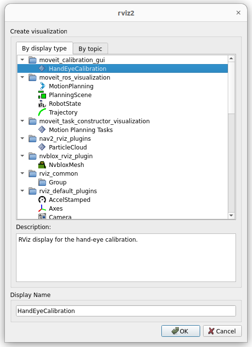
Cannot start: Robot is in Manual mode, switch the robot to Auto (Remote) mode, and relaunch this command. The driver does not retry on its own.In the RViz window that opens, select Add > By display type > moveit_calibration_gui > HandEyeCalibration. Select OK to add the calibration panel to the window. Verify that a new panel titled HandEye Calibration appears on the left side of the RViz window.
In the HandEye Calibration panel, select the Target tab and set the following parameters:
Target Type
HandEyeTarget/Charucosquares, X
Number of squares in calibration target along X direction
squares, Y
Number of squares in calibration target along Y direction
marker size (px)
1500square size (px)
2400margin size (px)
60marker border (bits)
Number of bits around marker border
ArUco dictionary
DICT_5X5_250longest board side (m)
Measured length of longest side of the board pattern in meters
measured marker size (m)
Measured length of marker in meters
If you use the calib.io calibration targets recommended in the Calibration Target section, you can use the following values directly:
Target Type
HandEyeTarget/Charucosquares, X
14squares, Y
9marker size (px)
1500square size (px)
2400margin size (px)
60marker border (bits)
1ArUco dictionary
DICT_5X5_250longest board side (m)
0.28measured marker size (m)
0.015After you set these values, select Create Target.
Finally, select the appropriate image topic from the Camera Image Topic drop-down menu. For RealSense, the topic is
/camera_1/color/image_raw.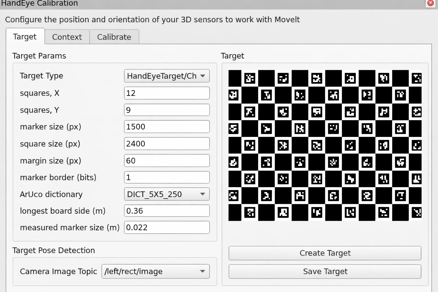
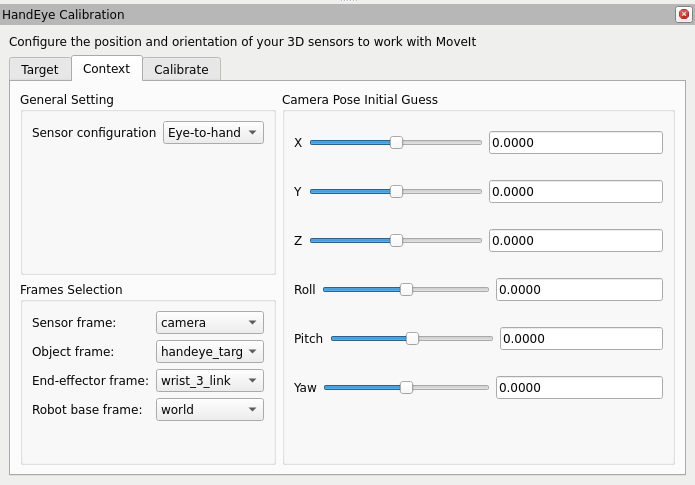
In the HandEye Calibration panel, select the Context tab and set the following parameters:
Sensor Configuration
Eye-to-hand
Sensor frame
camera_1_linkObject frame
handeye_targetEnd-effector frame
<ROBOT_SN>_flangeRobot base frame
worldNote
After you set Sensor frame, the UI can freeze for a few seconds before it becomes responsive again.
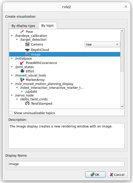
Add a panel to visualize the calibration target detection by selecting Add > By topic > /handeye_calibration > /target_detection > Image. Select OK to add the panel.
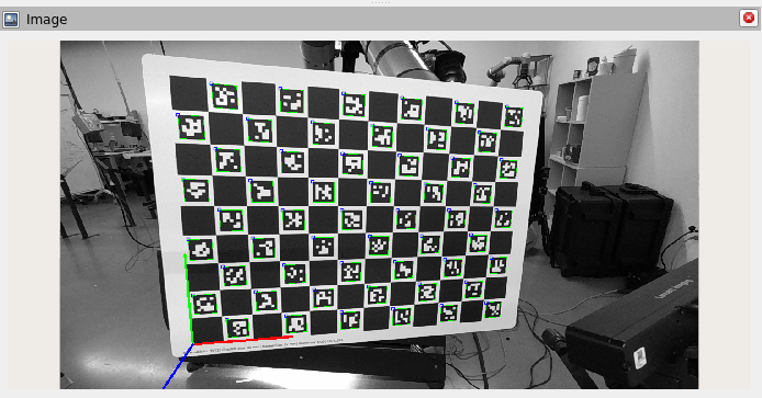
Verify that a new panel titled Image appears on the left side of the RViz window and shows the detected pose of the calibration target.
Add TF visualizations for the camera and target. In the RViz window, select Add > By display type > rviz_default_plugins > TF. Select OK to add the visualization to the window. Verify that a TF entry appears in the Displays panel on the left side of the window. Expand the TF entry, select Frames, and clear All Enabled. Scroll through the list of frames and re-enable
camera_1_linkandhandeye_target. These are the camera frame and target frame, respectively.In the HandEye Calibration panel, select the Context tab and use the sliders under Camera Pose Initial Guess to provide an initial pose estimation. Adjust the translation and rotation values until the TF visualizations on the right side of the window roughly match the physical positions of the camera and target board relative to the manipulator arm.
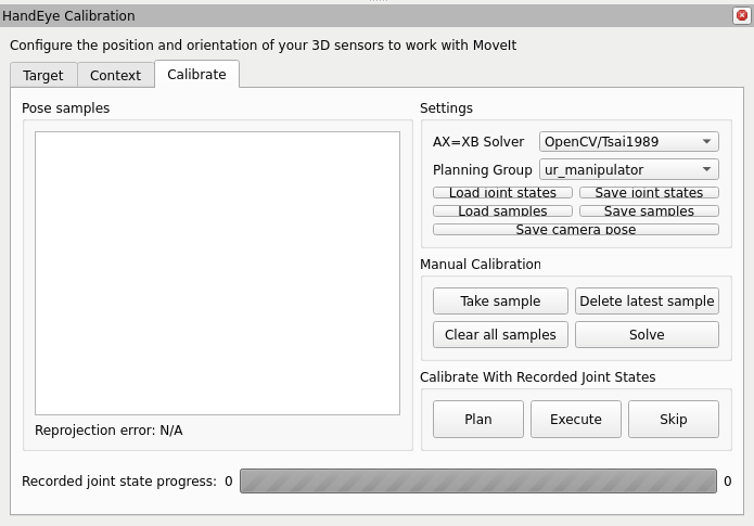
In the HandEye Calibration panel, select the Calibrate tab. Make sure the calibration board is visible in the camera image. Move the manipulator arm to a desired pose and select Take sample. If the sample succeeds, it appears in the box titled Pose samples. After you take at least five samples, the tool computes a camera pose and a corresponding reprojection error, which appears at the bottom left of the HandEyeCalibration window. Continue to move the manipulator arm and collect samples until you reach the desired number of samples.
Move the robot using the MotionPlanning panel in RViz:
In the RViz Displays panel, expand the MotionPlanning entry.
In the MotionPlanning panel at the bottom left, select the Joints tab.
Use the joint sliders to move individual joints to the desired position. RViz shows the planned pose as an orange overlay on the robot model.
Select the Planning tab, and then select Plan & Execute to move the robot to the new joint configuration.
Wait for the robot to finish moving before selecting Take sample in the HandEye Calibration panel.
Note
More diverse samples typically lead to a more robust calibration. Use at least two translational poses with approximately 10 rotations for each translation. Rotate the board along all three axes (roll, pitch, and yaw) at the same time so that each rotation differs sufficiently from the previous one. Add more rotations to improve the accuracy of the calibration. Keep the translational poses within the workspace of the manipulator arm.
Verify that reprojection error is low enough for your application, and that the camera position in RViz looks reasonable and aligns with the simulated robot. In testing, this procedure produced reprojection errors under 0.002 m and 0.002 rad.
After you take the desired number of samples, save the calibration results by selecting Save camera pose.
Note
Different solvers yield different calibration results. Experiment with different solvers to find the one that yields the best results for your use case. To select a different solver, open the drop-down menu next to AX=XB Solver and select the desired solver. Then select Solve to recompute the calibration results with the selected solver.
The
calibration.launch.pyoutput from the calibration tool includes a code snippet similar to the following example. The values are for illustration only and differ for each setup:""" Static transform publisher acquired via MoveIt 2 hand-eye calibration """ """ EYE-TO-HAND: world -> camera """ from launch import LaunchDescription from launch_ros.actions import Node def generate_launch_description() -> LaunchDescription: nodes = [ Node( package="tf2_ros", executable="static_transform_publisher", output="log", arguments=[ "--frame-id", "world", "--child-frame-id", "camera", "--x", "1.77278", "--y", "0.939827", "--z", "-0.0753478", "--qx", "-0.128117", "--qy", "-0.0317539", "--qz", "0.955077", "--qw", "-0.265339", # "--roll", # "0.132507", # "--pitch", # "-0.229891", # "--yaw", # "-2.5843", ], ), ] return LaunchDescription(nodes)
You can now use the calibrated pose values with the rest of the Isaac for Manipulation suite by updating the values in static_transforms.launch.py as described in Configure Cameras for DisplayPort Insertion. Specify the camera frame name from that configuration in the
--child-frame-idfield. For dual-camera setups, use a different frame name for each calibrated camera.
Validating Calibration#
To validate the calibration, run the following procedure.
Perform two calibrations for the same camera. Use the resulting transforms to create a JSON file with the following schema. The third entry is optional. Include it only if you performed a third calibration with another imager.
[
    {
        "parent_frame": "world",
        "child_frame": "camera_1_link",
        "translation": {
            "x": -0.412198,
            "y": 0.238021,
            "z": 0.138175
        },
        "rotation": {
            "x": -0.0527208,
            "y": -0.00452152,
            "z": 0.998266,
            "w": -0.0257981
        },
        "imager_used": "rgb_realsense"
    },
    {
        "parent_frame": "world",
        "child_frame": "camera_1_link",
        "translation": {
            "x": -0.413251,
            "y": 0.235007,
            "z": 0.132836
        },
        "rotation": {
            "x": -0.0524579,
            "y": -0.00387522,
            "z": 0.998361,
            "w": -0.0225519
        },
        "imager_used": "realsense_infra2"
    },
    {
        "parent_frame": "world",
        "child_frame": "camera_1_link",
        "translation": {
            "x": -0.413318,
            "y": 0.234351,
            "z": 0.132421
        },
        "rotation": {
            "x": -0.0525905,
            "y": -0.00255462,
            "z": 0.99835,
            "w": -0.0229073
        },
        "imager_used": "realsense_infra1"
    }
]
Save this file, and then set the following environment variables:
export CALIBRATION_TRANSFORMS_FILE=/path/to/your/calibration_transforms.json
export ENABLE_MANIPULATOR_TESTING=manual_on_robot
The validation script first records a calibration dataset that stores the following:
RGB and infrared camera streams
TFs, which store the extrinsic calibration from the robot to the camera and the inter-camera transforms between the RGB and infrared streams
Camera information, which records the camera intrinsics
The script then runs a test that visualizes errors in the following:
Target pose estimation with the OpenCV Perspective-n-Point (PnP) solver
The factory-calibrated intrinsic transforms between the RGB and infrared streams
The error bounds of the calibration process from two extrinsic calibrations
Before you run the calibration data recording script, confirm the following:
The camera can see the calibration target, and the target is static.
The target fills as much of the camera’s field of view as possible.
Run the following command. It records data for 60 seconds and then runs the test.
export ENABLE_MANIPULATOR_TESTING=manual_on_robot
export ISAAC_ROS_MANIPULATION_TEST_CONFIG=/path/to/flexiv_rizon4s_grav_displayport_cable_insertion.yaml
export NUM_SQUARE_HEIGHT=9
export NUM_SQUARE_WIDTH=14
export LONGER_SIDE_M=0.28
export MARKER_SIZE_M=0.015
bash $(ros2 pkg prefix --share isaac_ros_manipulation_bringup)/test/run_calibration_validation.sh
The script writes JSON files and images that visualize the error to the output folder set in
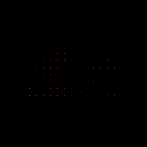
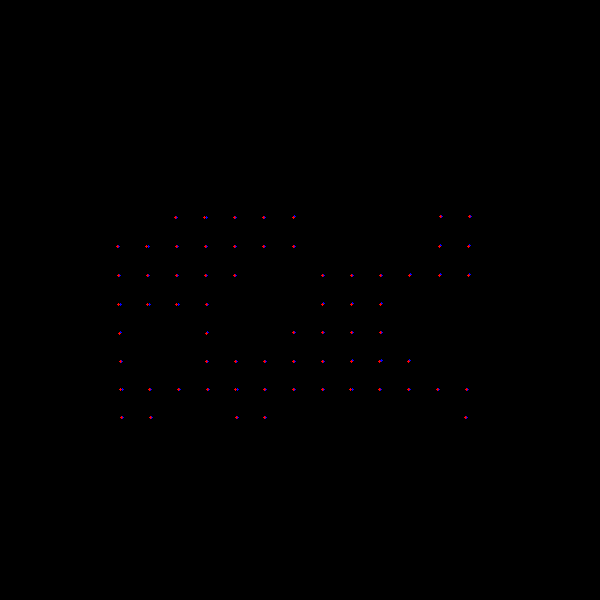
run_calibration_validation.sh. The JSON output is similar to the following:"extrinsics_error": { "error_mean_x_cm": -0.8119825981623039, "error_std_x_cm": 0.004882939882471144, "error_mean_y_cm": -0.558025644231066, "error_std_y_cm": 0.004597599422036537, "error_mean_z_cm": 0.3173449385777736, "error_std_z_cm": 0.04592212495318613, "projected_frame": "camera_1_infra2_optical_frame", "home_frame": "camera_1_infra1_optical_frame", "notes": "This error is the same as above dict however we now use the extrinsics transform 1 calibration point to world and another one used for world back to camera_1_link instead of using the target pose estimation error" }Most importantly, review the images to observe how the error increases as the pose estimation adds more computation: first the OpenCV solver, then the intrinsics, and then the two extrinsic calibrations.
The following image shows the visualized OpenCV pose error. Only red dots are visible because the projected blue dots match the pixel values exactly.
The following image shows the error after you add the intrinsics calibration. A small error starts to appear.
The following image shows the error after you add the two extrinsic calibrations. The error is larger. In the image, the error is about half the size of a 2 cm corner square, or about 1 cm. Across the full camera-to-target chain, the worst-case error is about 1.5 cm. This number is inflated because the errors in the two calibrations compound, so the actual error might be closer to 5 mm.
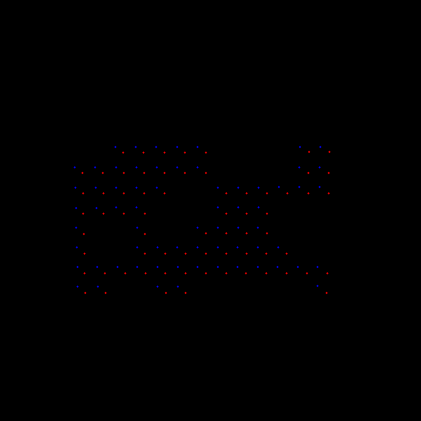
Careful calibrations with wide coverage can help reduce this error.
This also motivates the need for data-driven robotics algorithms that are robust to such errors in calibration.